LTPS-UM-8007-01, Issue 1
Installation
SPX-CABFIN01, SPX-CABFIN04
November 9, 2001
15
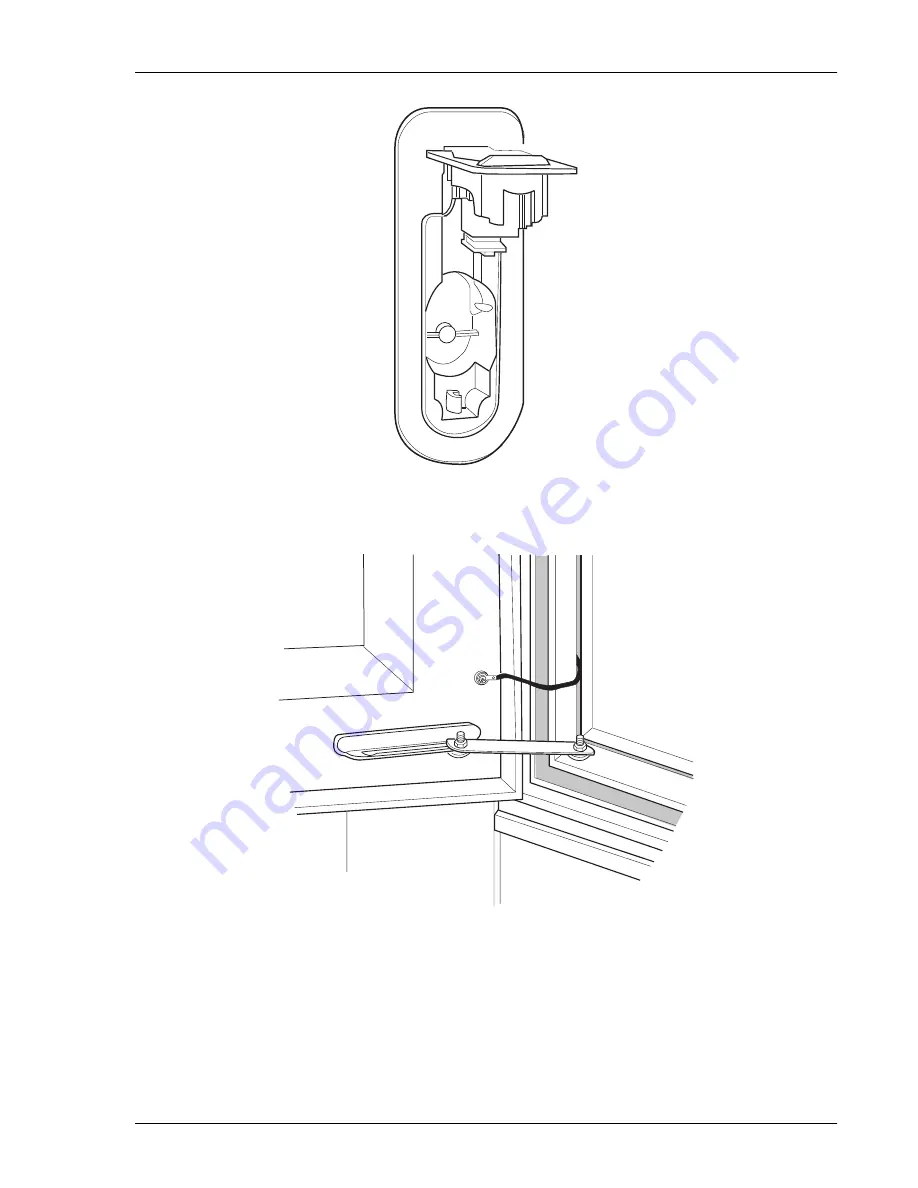
Figure 10.
Latch in Open Position
Figure 11.
Wind Latch
Page 1: ...Soneplex Soneplex USER MANUAL Soneplex Fiber Hub Cabinet Product Catalog SPX CABFIN01 SPX CABFIN04...
Page 2: ...nformation contained in this document is company private to ADC DSL Systems Inc and shall not be modified used copied reproduced or disclosed in whole or in part without the written consent of ADC Con...
Page 3: ...If the equipment has been damaged in transit immediately report the extent of damage to the transportation company and to ADC DSL Systems Inc Order replacement equipment if necessary Check the packing...
Page 4: ...of damage notify the freight carrier insurance company or ADC For safety and protection during shipment and storage the cabinet is shipped on a wooden pallet with plastic covering and an exterior corr...
Page 5: ...fiber ends properly to prevent cut fiber ends from being accidentally ingested or embedded in skin or eyes by humans or animals To avoid electrical shock exercise caution when working around power co...
Page 6: ...Cautions and Warnings LTPS UM 8007 01 Issue 1 vi November 9 2001 SPX CABFIN01 SPX CABFIN04...
Page 7: ...te Preparation 5 Preparing the Form 7 Pouring the Pad 9 Installation__________________________________________________________________________ 11 Before You Begin 11 Placing the Cabinet on the Pad 11...
Page 8: ...ystem Maintenance 59 Modular Power Supply Shelf Maintenance 60 Replacing the Rectifier Module 60 Replacing the Alarm and Control Assembly 60 Heat Exchanger Maintenance 61 Removing the Heat Exchanger 6...
Page 9: ...ABFIN AC Power Wiring Diagram 24 18 Battery Drawer Connector Locations 26 19 Connector Locking Spring 26 20 Battery Jumper Installed in Connector Bus 27 21 Battery Jumper Installed in Connectors 27 22...
Page 10: ...wer Wiring Diagram 47 42 AC Meter Socket Installed 49 43 Receptacle Protector 50 44 Heat Exchanger Air Flow 51 45 Master Fan Shelf 52 46 Typical Intrusion Alarm Switch 53 47 Temperature Compensation M...
Page 11: ...C Circuit Breaker Assignments 23 2 Rectifier Module Controls and Indicators 39 3 DC Circuit Breaker and Fuse Assignments 40 4 Alarm and Control Assembly Controls and Indicators 41 5 DC Distribution Pa...
Page 12: ...List of Tables LTPS UM 8007 01 Issue 1 xii November 9 2001 SPX CABFIN01 SPX CABFIN04...
Page 13: ...chamber with a heat exchanger cooling system a bulk power system and a side entrance splicing end or power end chamber a slide out battery drawer at the cabinet base The drawer is factory equipped wit...
Page 14: ...ectifiers provide for reliability and load sharing Figure 2 Modular Power Supply Shelf The power supply shelf requires nominal 208 240 Vac 60 Hz input power maximum power consumption is 3 101 watts In...
Page 15: ...ure compensation module Selective HVSD and Restart The selective HVSD is measured at the ACA front panel HVSD and VOLTS X10 test points and can be adjusted at the HVSD VOLT ADJ control If the DC outpu...
Page 16: ...aring the Form on page 7 Pouring the Pad on page 9 SITE SELECTION Consider the following when deciding on the SPX CABFIN cabinet location Right of Way It should be the practice of any installing compa...
Page 17: ...cted The cabinet is installed on a concrete pad that is cast in place The foundation pad should be made of concrete only substitute materials such as reinforced plastics lack the rigidity required by...
Page 18: ...ng a minimum of 6 inches 152 mm of sand or gravel 7 For excavated pad applications excavate a hole for the pad and cable conduits in accordance with the engineering work prints generally to a depth of...
Page 19: ...und the proposed foundation pad location according to local practices and building safety codes 3 Lay the SPX CABFIN cabinet template on the ground over the conduits and slip the conduits or cables in...
Page 20: ...m as shown in Figure 6 on page 9 10 Place the template s in the form and fasten the template s to wooden stakes 11 Position the conduit and cable as required in the cable entry box es or appropriate t...
Page 21: ...insects refer to local practices Figure 6 Foundation Pad Design POURING THE PAD The concrete compression strength must be a minimum of 4 000 psi as determined by ASTM C39 Test of Compression Strength...
Page 22: ...of the form 3 Pour the concrete Puddle the concrete along all edges of the form 4 Finish the concrete so that it is flush with to 1 4 inch 6 mm below the top of the template mounting plates The pad sh...
Page 23: ...Observe the following safety measures when placing the cabinet Before lifting the cabinet block off the area Vehicles should not be parked within 25 feet 6 4m of the lifting circumference Keep bystan...
Page 24: ...ake up the cable slack with the crane 3 Attach a length of 5 8 inch diameter rope to a lifting eyebolt as a tagline 4 Remove the four pallet mounting bolts securing the cabinet to the pallet 5 Close a...
Page 25: ...Set the cabinet and slacken the slings so that the full weight of the cabinet is on the base 11 Install the four anchor bolts flat washers and lock washers Tighten all bolts 12 Remove the slings and t...
Page 26: ...gure 9 The latch is spring loaded and will rise from the latch bed 2 Raise the latch to the fully open position and open the door as shown in Figure 10 on page 15 3 To secure the wind latch as shown i...
Page 27: ...LTPS UM 8007 01 Issue 1 Installation SPX CABFIN01 SPX CABFIN04 November 9 2001 15 Figure 10 Latch in Open Position Figure 11 Wind Latch...
Page 28: ...by removing one bolt at each end of the battery tray and one bolt beneath the front center of the end chamber floor as shown in Figure 12 and Figure 13 on page 17 Figure 12 Skirt Mounting Bolt in Batt...
Page 29: ......
Page 30: ...able s 8 Secure any remaining unused nozzle in position on the bottom plate 9 Pull the ground wire s through the grommet and route it in a smooth curve to the ground bar as shown in Figure 13 on page...
Page 31: ...e all safety precautions as specified by local building codes and the National Electrical Code NEC If local building codes specify procedures different from those in this section follow local codes Be...
Page 32: ...mp on the cable Connect a solid 6 AWG ground wire between the clamp and the cabinet ground bar Place the ground wire under the containment bracket at the front of the end chamber floor 8 Install binde...
Page 33: ...s to properly terminate and arrange the fibers refer to the instructions inside the bag 3 Open the termination shelf cover Do not directly view the end of any energized fiber Wear laser safety glasses...
Page 34: ...support about 3 inches 76 mm below the bottom of the termination shelf 6 Bond the metallic cable members to the frame using a 6 AWG ground strap 7 Following local practices route the fiber cables into...
Page 35: ...o could result in serious injury and equipment damage Before applying commercial AC power to the cabinet ensure that no AC power plugs have been connected to the auxiliary AC receptacles Do not procee...
Page 36: ...erforming the following steps to avoid electrical shock hazardous voltages are present To metered over current projected single phase 120 240 service shown for reference only wires installed in field...
Page 37: ...ove the battery drawer cover below bay 1 2 Slide out the battery drawer remove any loose parts packages 3 While facing the front of the battery drawer as shown in Figure 18 on page 26 locate the two c...
Page 38: ...from the cabinet The cable ends must be cut and thoroughly insulated from each other and from the cabinet if the cables are not completely removed These cables are terminated at the battery terminati...
Page 39: ...have been removed push the jumper terminals into the connectors so that they lock in place The installed battery jumper is shown in Figure 20 and Figure 21 Figure 20 Battery Jumper Installed in Conne...
Page 40: ...high short circuit current Remove rings watches and other jewelry Although the voltages encountered are not hazardous the batteries can deliver large amounts of current Do not smoke permit open flames...
Page 41: ...e make a note of the calibration voltage written on the module Install the first battery in the battery drawer near the battery temperature compensation module leads as shown in Figure 22 Label locati...
Page 42: ...ce Trim any excess cable tie 10 Push the battery with the temperature compensation module into its installed position Figure 24 on page 31 Connect the plug ended leads from the module to the mating pl...
Page 43: ...asher and install but do not tighten the terminal nut 15 At the negative battery terminal attach the other lead from battery cable Do not loosen the large hex nut at the base of the terminal stud Do n...
Page 44: ...nd install but do not tighten the terminal fastener screw or nut 20 Position the battery cable ends as shown in Figure 25 or Figure 26 on page 33 Tighten both battery terminals to a torque of 65 70 in...
Page 45: ...ons shown in Figure 27 on page 34 or Figure 28 on page 34 For ease in connecting the battery cables and TSUs later place all batteries in the same position as the first battery negative terminals near...
Page 46: ...covers Step 2 locate and remove the thin walled panel at the center of the short side of the cover as shown in Figure 29 on page 35 Using pliers flex the panel until it snaps off For 6V batteries conn...
Page 47: ...attery disconnect by inserting the pin provided at the right hand side into the BATTERY DISCONNECT jack shown in Figure 30 on page 36 or Disconnect any one connector from the battery connector bus for...
Page 48: ...are too short remove any protective covers from the batteries and connect the DMM probes to the battery terminals at the ends of the string P N 73 16 606 1 2 48V 48V 48V RTN RTN 48V MAX BREAKER 30A RT...
Page 49: ...two 12V strings continue with Step 7 7 If two 12V battery strings are used reconnect all battery bus connectors for the second string under test and isolate the second string At the DC distribution pa...
Page 50: ...ailure to do so could result in serious injury and equipment damage Use an ESD wrist strap to prevent static discharge An ESD ground connection is provided on the multiplexer shelf A Fluke 79 Digital...
Page 51: ...INPUT circuit breaker Lighted red if a failure disables the rectifier A failure condition also activates the alarm relay connected to the cabinet Power Minor PMN alarm input Failure conditions include...
Page 52: ...lex Shelf 2 A CB 4 Soneplex Shelf 2 B CB 5 Soneplex Shelf 3 A CB 6 Soneplex Shelf 3 B Fuses GMT Type 15A max FUSE 1 MUX A FUSE 2 MUX B FUSE 3 FAN TRAY A FUSE 4 FAN TRAY B FUSE 5 not used FUSE 6 MASTER...
Page 53: ...se jacks indicate 1 10 actual voltage HVSD VOLT ADJ Potentiometer Used to adjust the voltage at which a rectifier module shuts down if the module is delivering more than 10 of rated load BAT ON DISCH...
Page 54: ...remote alarms are extended FUSE PANEL Fuses 15A max Refer to Table 6 on page 52 FUSE ALARM Red LED Lighted when any fuse has failed or when either circuit breaker is set to OFF or tripped BATTERY DISC...
Page 55: ...Figure 38 on page 44 9 Locate remote alarm connector P1 connect P1 to ACA connector J1 the side connector nearest the front of the ACA Access to J1 is through the shelf side opening 10 Reinstall the...
Page 56: ...he RTN terminal below an installed circuit breaker as shown in Figure 39 Figure 39 Battery Voltage Test Points Measure the air temperature in the area of the battery temperature compensation module Us...
Page 57: ...voltage marked on the battery temperature compensation module The module marking was noted in DLP 403 20 Using a DMM measure the calibration voltage at rectifier module No 1 CAL VOLTS and jacks Leave...
Page 58: ...14 The DMM indicates rectifier No 2 output 27 Verify that the rectifier output voltage is within 0 1 Vdc of the value found on the chart in Step 15 28 Use the DMM to measure the calibration voltage a...
Page 59: ...N If it is necessary to adjust the intrusion alarm switches refer to Adjusting the Intrusion Alarm Switch on page 52 GND MUX RECTIFIER TO BATTERY STRING DC DISTRIBUTION LVD PANEL 48VB GND 48VA 48V 1 2...
Page 60: ...nd the generator 4 At the power transfer cabinet remove the cover from the female receptacle located on the outside of the power transfer cabinet as shown in Figure 42 on page 49 5 Remove the protecto...
Page 61: ...vember 9 2001 49 Figure 42 AC Meter Socket Installed 7 Connect the plug from the AC generator to the power transfer cabinet receptacle 8 Set the power control switch to the GENERATOR down position to...
Page 62: ...Installation LTPS UM 8007 01 Issue 1 50 November 9 2001 SPX CABFIN01 SPX CABFIN04 Figure 43 Receptacle Protector Collar Protector...
Page 63: ...of the electronics chamber and exhausts it into the bottom of the chamber Figure 44 Heat Exchanger Air Flow To verify heat exchanger fan operation 1 Locate the heat exchanger fan control switch as sh...
Page 64: ...the door with sufficient plunger travel to disarm the alarm when the door is closed but without interfering with the door closing completely 3 If necessary repeat Step 1 and Step 2 Table 6 Master Fan...
Page 65: ...der screw is properly adjusted tighten the extender screw locknut 5 Repeat Step 1 through Step 4 for each intrusion alarm switch To disarm the alarm switch and reset the alarm card when the door is op...
Page 66: ...by one or both of the following conditions Manual or automatic operation of the DC OUTPUT circuit breaker on either rectifier Manual or automatic opening of two or more DC load circuit breakers on the...
Page 67: ...are clean and the connections are tight 5 If necessary clean and tighten the terminals in accordance with local practices using approved cleaning solutions 6 Reapply No Ox compound and replace each b...
Page 68: ...ot hazardous the batteries can deliver large amounts of current Do not smoke permit open flames or cause sparks near a battery Do not allow metallic objects to rest on the batteries or fall across the...
Page 69: ...attery so that it will fit under the battery connector bus Tighten the cable ties securely and verify that the module is held firmly in place Trim any excess cable tie 12 Place the new battery in the...
Page 70: ...in the string 23 Repeat Step 4 through Step 22 for the second battery string 24 Plug the battery bus connector into the connector bus at the front of the drawer 25 Using a DMM measure the battery str...
Page 71: ...48 1 Protective fuse caps Lorain Part No 248898700 are available for alarm type fuses F1 through F4 If fuse replacement becomes necessary remove the fuse cap from the old fuse and place it on the new...
Page 72: ...to OFF 8 Adjust the float voltage on the new rectifier as shown in Figure 40 on page 45 9 At the other rectifier module first set the DC OUTPUT circuit breaker to ON then set the AC INPUT circuit brea...
Page 73: ...connector as shown in Figure 49 on page 62 2 Release the two draw latches at the top left and right sides of the heat exchanger The heat exchanger will drop about one half inch 3 Release the two draw...
Page 74: ...it in its vertical position bring it out of the cabinet The top fan assembly will drop so that the shoulder rivet is at the top of the retaining slot 6 Hang the heat exchanger on the inside of the ope...
Page 75: ...UM 8007 01 Issue 1 Appendix A Maintenance SPX CABFIN01 SPX CABFIN04 November 9 2001 63 Figure 50 Heat Exchanger Supported on End Chamber Door Bottom fan Heat exchanger hanging on open splice chamber...
Page 76: ...at each back corner and one centered at the front 3 When the fan assembly has cleared the rear rivets allow it to drop straight down onto the fan rails 4 Slide the fan assembly out from the cabinet 5...
Page 77: ...he top fan assembly Keep the heat exchanger aligned vertically 3 Align the bottom of the heat exchanger over the lower plenum Pay special attention to the alignment of the draw latches and locking cli...
Page 78: ...eceptacle Rotate the collar behind the protector as necessary to secure the protector as shown in Figure 52 Figure 52 Receptacle Protector 6 Set the power control switch to the up position to return t...
Page 79: ...LTPS UM 8007 01 Issue 1 Appendix A Maintenance SPX CABFIN01 SPX CABFIN04 November 9 2001 67 Figure 53 AC Meter Socket Installed AC meter Power cabinet Receptacle cover...
Page 80: ...ipment was purchased You will need to provide this number to ADC Customer Service to obtain a return authorization 2 Call ADC Customer Service to ask for a Return Material Authorization RMA number and...
Page 81: ...ng information Company name address telephone number and the name of a person Customer Service can contact regarding this equipment A description of the equipment as well as the number of units that y...
Page 82: ...Appendix B Product Support LTPS UM 8007 01 Issue 1 70 November 9 2001 SPX CABFIN01 SPX CABFIN04...
Page 83: ...fects under normal use ADC will replace defective media at no charge if it is returned to ADC during the 30 day warranty period along with proof of the date of shipment The transportation charges for...
Page 84: ...ificated Firm ADC DSL Systems Inc 14402 Franklin Avenue Tustin CA 92780 7013 Tel 714 832 9922 Fax 714 832 9924 Technical Assistance Tel 800 366 3891 x73223 Tel 952 917 3223 Fax 714 832 9924 DOCUMENT L...