Wire Rope Hoist
PAGE: 46
Model WR
WR-0214
2721 NE 4
th
Ave Pompano FL, 33064 | (954) 367-6116
Visit WWW.ACIHOIST.COM for the most current information
3.
Lift the load a few inches and stop the hoist. If brakes stop and hold the load, continue lifting and lowering the
load several feet, stopping the hoist several times in each direction to check that the hoist braking system stops
and holds the load.
4.
If the hoist braking system stops and holds the load, the hoist operates in accordance with the control devices,
and no unusual sounds are present during operation, the hoist is ready to be released for operating purposes.
5.
If the hoist braking system does not stop and hold the load, the hoist does not operate in accordance with the
control devices, or any unusual sounds are present during operation, the hoist is not ready to be released for
operating purposes; and corrective action must be taken.
6.5 Repair
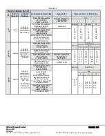
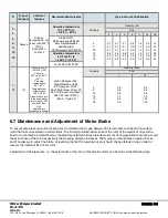
If maintenance, adjustment, replacement of parts, or repair of the hoist is required because of any damage or
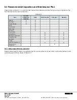
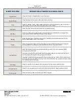
malfunctions noted during the daily, frequent, or periodic inspections outlined in the Inspection section of this manual;
because of conditions found during a hoist test as outlined in the Test section of this manual; or based upon specific
instructions outlined in other sections of this manual; the hoist shall be taken out of service, and maintenance performed
as required.
Repairs include removal of small defects noticed during the inspections, such as: damages of the cables or light
activities as replacement of contactors and relays. They don't include harder and more responsible activities that must be
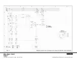
coordinated with the producer, such as: change in the electric diagram or implementation of additional devices.
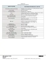
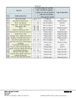
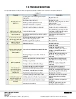
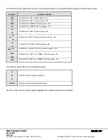
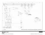
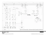
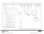
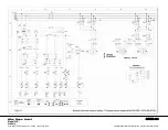
The possible failures in the electric equipment and troubleshooting are listed in Table 22.
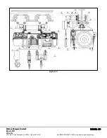
Follow the instructions outlined in various sections of this manual for specific components or portions of the hoist where
maintenance or adjustment is required. Refer to the parts identification pages for the specific portion of the hoist where
maintenance or adjustment is being performed and to identify any part numbers requiring replacement.
If any instructions are not clear; or if any additional information is required in reference to adjustment, maintenance, or
identification of parts; contact ACI Hoist & Crane or the distributor of the hoist.
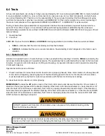
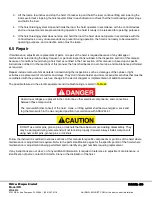
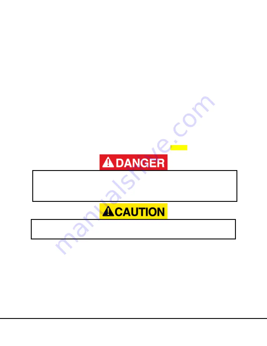
Hazardous voltages are present in the control box, other electrical components, and connections
between these components.
The main switch (disconnect) of the hoist, crane, or lifting system shall be de-energized. Lock and
tag the main switch in the de-energized position in accordance with ANSI Z244.1.
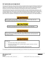
DO NOT use cotter pins, groove pins, or locknuts that have been removed during disassembly. They
may be damaged during removal and will not function properly if reused. Always install components
using new cotter pins, groove pins, or locknuts

