Wire Rope Hoist
PAGE: 45
Model WR
WR-0214
2721 NE 4
th
Ave Pompano FL, 33064 | (954) 367-6116
Visit WWW.ACIHOIST.COM for the most current information
the upper gravity limit switch requires adjustment or replacement. If adjustment of the gravity type upper limit
device is required, refer to the LIMIT SWITCHES section of this manual.
Operate the hoist in the lowering direction until the load block reaches its lowest point of travel. At this
location of the load block two wraps of wire rope must remain at each anchorage on the hoist drum. IF LESS
THAN TWO WRAPS REMAIN AT EACH ANCHORAGE ON THE DRUM, DO NOT USE THE HOIST AT THIS
LOCATION. Contact ACI Hoist & Crane or the distributor of the hoist.
c.
If a geared limit switch is specified and furnished on the hoist, operate hoist in the lowering direction until motion
of the load block stops to check lower geared limit device circuit. While lowering the load block, watch the wire
rope paying off the drum. If all the wire rope will pay off the drum before the lower geared limit device stops load
block motion, STOP hoist motion as the lower geared limit device requires adjustment. The hoist lower geared
limit device is set at the factory to stop lower travel of the load block with two wraps of wire rope remaining at
each anchorage on the drum. ASME B30.16 allows one wrap of wire rope remaining at each anchorage on the
drum when a lower limit device is used. It is recommended that the lower geared limit device be set to prevent
the load block from resting on the floor and allowing the hoisting ropes to go slack. If adjustment of the lower
geared limit device is required, refer to the LIMIT SWITCHES section of this manual.
d.
If a geared limit switch is specified and furnished on the hoist, operate hoist in the raising direction to a point
where the block is about 12 inches below the hoist drum. If the hoist has more than one speed, continue to raise
at low speed or; if hoist is a single-speed unit, inch the load block in the raising direction until motion of the load
block stops to check upper geared limit switch circuit. If the load block will hit the weight of the gravity type
upper limit switch before the upper geared limit device stops load block motion, STOP hoist motion as the upper
geared limit device requires adjustment. The hoist upper geared limit device is set at the factory to stop upper
hook travel when the top of the load block is two inches below the weight of the gravity type limit switch. If
adjustment of the upper geared limit device is required, refer to the LIMIT SWITCHES section of this manual
.
6.4.2 Load Test:
All hoists in which load suspension parts have been altered, replaced, or repaired SHALL be dynamically tested by the
owner/user before being placed in operational service. The toad test shall be conducted under the direction of a
designated person and a record of the test should be made. The test load applied to the hoist shall be at least equal to
the rated load capacity of the hoist, or greater as approved by the hoist manufacturer. Functions to be performed during
the load test include: (1) operation of control devices; (2) lifting and lowering; and (3) operation of brakes.
Load test steps are as follows:
1.
Attach test load to the hoist hook. Test load shall be at least equal to the rated load capacity of the hoist. ACI will
authorize the use of a hoist test load equal to 125% of the rated load capacity of the hoist for load test purposes
only.
2.
Before lifting the load, operate the hoist in the lifting direction to take any slack out of the hoist wire rope.
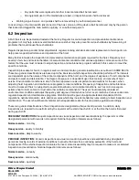
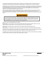
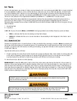
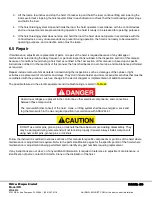
Geared upper limit device must be adjusted so that when it is tripped, there is a minimum of 2 inches
between the top of the load block and the gravity type upper limit switch.
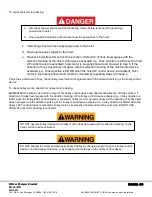
Never operate hoist without the protection of properly functioning limit switches.

