


Wire Rope Hoist
PAGE: 15
Model WR
WR-0214
2721 NE 4
th
Ave Pompano FL, 33064 | (954) 367-6116
Visit WWW.ACIHOIST.COM for the most current information
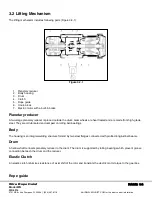
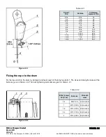
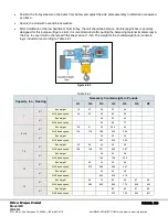
The rope guide is essential to extend the cable life and reduce maintenance costs. The rope guide consists mainly of two
parts – a guide nut and a tensioning spring which ensures that the rope runs firmly on the rope drum. The rope guide is
designed to allow for a ± 4° vertical wire rope deviation. The rope guide actuates the upper and lower end limit switches.
No special tools are required for the replacement of the rope guide.
Hook- block
A hook block allows for a considerable amount of flexibility and safety in lifting operations. Semi-lids of the block cover
the rollers and have the necessary hardness and strength against impact with stationary solid objects.
Electric motor with a built-in brake
The motor used in ACI hoist is a TEFC (Totally Enclosed Fan Cooled) conical rotor construction, 3 phase induction type.
The motor is constructed with a small fan on the rear shaft of the motor, covered by a housing. This fan draws air over
the motor fins, removing excess heat and cooling the motor. The enclosure is "Totally Enclosed". This ordinarily means
that the motor is dust tight. This fan-cooled externally mounted, tapered rotor motor is designed for high duty cycle
factors.
Energizing the motor causes the axial forces in the magnetic field to pull in the rotor into its correct running position and it
operates like a normal induction motor. When the motor is shut off, the return spring pushes the rotor assembly, including
the brake disc back into the conical brake surface, braking the motor and the load. This safe and simple braking
arrangement which does not require additional coil or electric circuitry is very reliable and needs very little or almost no
maintenance. Conical rotor brake has only one moving part, which is very easily accessible, and serviceable.
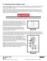
Control Box
Control box is a separate assembly unit including circuit closers for control of the lifting mechanism and traveling
mechanism, reducing transformer, push button and some other elements concerning special executions (main circuit
closer, rectifier for the auxiliary brake, electronic block for the load limiter, etc.).
Standard hoist and trolley motors are reconfigurable for 230 volt or 460 volt, three phase, 60 Hz. operation. Hoist and
trolley with other voltages and frequencies will be provided as an option. The voltage used in the operating circuit is safe
110 V obtained by means of reducing transformer. Control is executed by pendant push button in which electric and
mechanical interlock among the buttons for several of movements of the lifting mechanism and the electric trolley is
provided.
For protection against short circuit in the operating circuit a safety fuse is provided. On customer's request two fuses can
be provided. In the same circuit the limit switch is connected for both directions of movement of the hook. When the first
stage of the switch for a given direction is actuated the movement of the hook in the opposite direction is not blocked
and actuating the second stage blocks the movement in both directions because the main contactor switches off. A
latchkey for switching of the operating circuit is provided in the electrical equipment of the electric hoist.
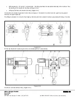
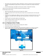
3.3 Trolley Traveling Mechanism
Hoist can be suspended to a trolley to provide horizental motion along a beam. Suspension of hoist from a trolley can be
as followed:
Stiff suspension - normal headroom at number of rope falls 2/1 and 4/1.The lifting mechanism is assembled
under the travelling mechanism (Figure 3.3.1A)
Swinging - the lifting mechanism swings in certain limits around an axis parallel to the monorail track (Figure
3.3.1B)
Joint - in addition apart from the lifting mechanism the travel wheels pairs can rotate around a vertical axis
(Figure 3.3.1B I)


