Wire Rope Hoist
PAGE: 54
Model WR
WR-0214
2721 NE 4
th
Ave Pompano FL, 33064 | (954) 367-6116
Visit WWW.ACIHOIST.COM for the most current information
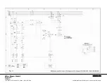
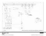
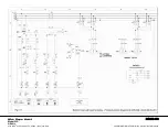
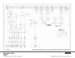
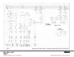
8.0 WIRING DIAGRAMS
Generally, for the control of the electric hoists reversive electric diagrams are used.
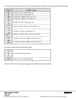
Meaning of designations are as follows:
L1
.
L2
,
L3
- electric network phases
S1
- stop button
T1
- transformer
F1
,
F2
,
F3
- safety fuses
Q
- Main contactor
Push buttons:
S2
- control cut-out switch button for LOWERING
S3
- control cut-out switch button for LIFTING
S4
- control cut-out switch button for RIGHT movement
S5
- control cut-out switch button for LEFT movement
S6
- end switch
M
- Electric motor
K1-K8
– contactors
K9
– contactor time relay
B1
- load limiter electronic block


