Wire Rope Hoist
PAGE: 44
Model WR
WR-0214
2721 NE 4
th
Ave Pompano FL, 33064 | (954) 367-6116
Visit WWW.ACIHOIST.COM for the most current information
To correct trolley motor phasing:
c.
Interchange any two lines supplying power to the trolley motor only. DO NOT reverse main power leads to the
hoist as this will also effect the phasing of the hoist motor.
d.
Re-energize power supply to the hoist.
e.
Re-check trolley travel for correct trolley motion. If direction of trolley travel agrees with the direction marking of
the trolley control device activated (i.e., trolley direction is LEFT when the trolley LEFT control device is
activated), trolley motor is properly phased. If the direction of trolley travel does not agree with the direction
marking of the trolley control device activated (i.e., trolley direction is RIGHT when the trolley LEFT control device
is activated), trolley motor is improperly phased and must be corrected by repeating steps a through e.
Operate hoist in the raising and lowering direction, without load on the hook, and stop motion to check operation of the
motor brake. The drift of the hook should not exceed one inch in either direction. If hook drift exceeds one inch, the
motor brake requires adjustment. Refer to the MOTOR BRAKE section of this manual for instructions on motor brake
adjustment.
Check operation of limit switches as follows:
a.
All checking of limit switches should be accomplished without a load on the hook. All checking of limit switches
should be accomplished by using the low speed of multiple-speed hoists, or inched into the limit if the hoist is a
single-speed unit.
b.
Hoists with the standard gravity type upper limit switch:
Check the gravity type upper limit switch by operating the hoist in the lifting direction. While the load block is
raising, lift the weight of the upper gravity type limit switch manually until motion of the load block stops.
Lifting the weight higher should cause the load block to lower until the weight is released. If raising motion
does not stop when the weight is lifted, STOP hoist motion as the upper gravity limit switch requires
adjustment or replacement. The lowering motion achieved by lifting the weight after raising motion of the
load block has stopped is a reverse plugging feature to minimize the possibility of the load block striking the
hoist frame or drum if the motor brake is out of adjustment. If adjustment of the gravity type upper limit
switch is required, refer to the LIMIT SWITCHES section of this manual.
Operate hoist in the lifting direction to a point where the block is about 12 inches below the hoist drum. If the
hoist has more than one speed, continue to raise at low speed or; if hoist is a single-speed unit, inch the load
block in the lifting direction until motion of the load block stops to check that load block stops when
Striking the weight of the gravity upper limit switch before striking any other part of the hoist. If the load block
will hit any part of the hoist prior to striking the weight of the gravity type limit switch, STOP hoist motion as
a.
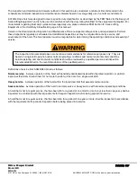
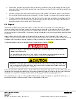
Disconnect power and lockout disconnecting means before reconnecting (reversing) power
lines to trolley.
b.
Only a qualified electrician should reconnect the power lines to the trolley.
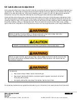
Disconnect power and lockout disconnecting means before adjusting limit switches. Limit switches
should be adjusted using a continuity tester or other type of tester that will indicate open or closed
circuits without the need of electrical power.
Only a qualified electrician should adjust switches.

