Wire Rope Hoist
PAGE: 52
Model WR
WR-0214
2721 NE 4
th
Ave Pompano FL, 33064 | (954) 367-6116
Visit WWW.ACIHOIST.COM for the most current information
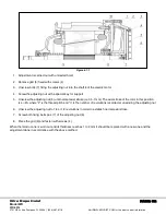
Figure 6.7.1
1.
Adjustment is carried out with unloaded hoist
2.
Remove grid (5) fixed with screws (4)
3.
Unscrew bolts (7) fixing the adjusting nut 6 to the shaft 8 of the electric motor
4.
Screw the adjusting nut with a special key for support
5.
Unscrew the adjusting nut (6) until normal axial stroke (i.e 0.5- 1mm). The axial stroke of the rotor in this position
is L=2n, where "2" is the thread pitch and "n" is the number of revolutions recorded at unwinding the adjusting nut
6.
Unscrew the adjusting nut to 1/4 or 1/2 revolutions in order to establish normal axial stroke
7.
Screw both fixing bolts pos. (7) of the adjusting nut (6)
8.
Place the grid (5) and fasten with screws (4)
When the ferodo cone is worn out and its thickness reaches 1 to 2 mm it should be replaced with a new one and the
adjustment done in accordance with the above method.

