


Chapter 3
42
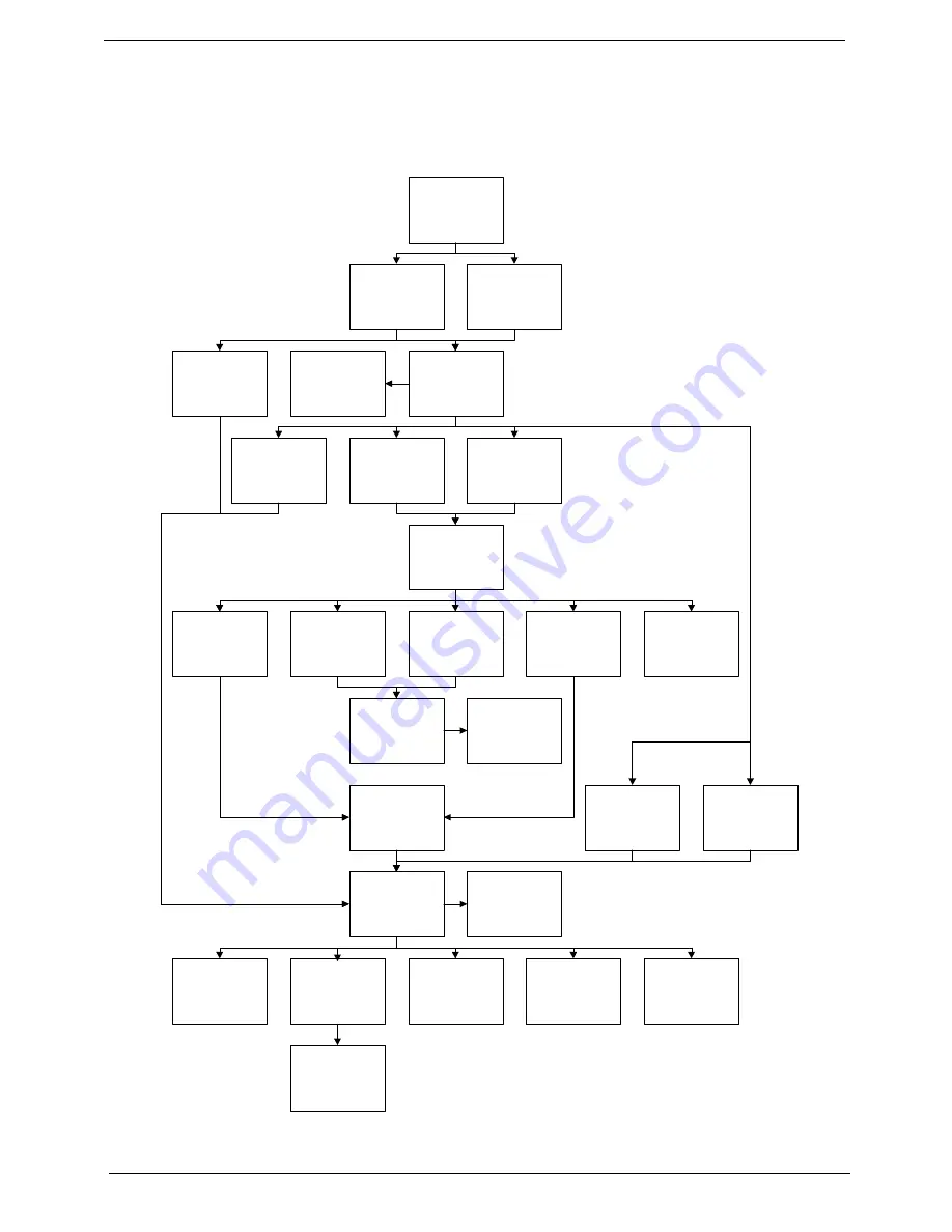
Disassembly Process
Disassembly Flowchart
Remove
Inverter Board
Remove
HDD Module
Turn off power and
disconnect all
cables before
proceeding
Remove
Stand Assembly
Remove
Rear Cover
Remove
ODD Bezel
Remove
TV Module
Remove
Speakers
Remove
Bluetooth Module
Remove
WLAN Board
Remove
FAN
Remove
Mainboard Shield
Remove
Mainboard
Remove
VGA Board
Remove
Audio Board
Remove
USB Board
Remove
LCD Panel
Remove
IR Receiver
Remove
Home Button
Board
Remove
ODD Module
Remove
DIMM Module
Remove
Thermal Module
Remove
CPU
Remove
Frame
Remove
Power Board
Remove
Antennas
Remove
Webcam
Remove
Touchscreen
Board
Summary of Contents for Z5700 Series
Page 6: ...VI ...
Page 10: ...X Table of Contents ...
Page 32: ...22 Chapter 1 ...
Page 55: ...45 Chapter 3 5 Lift the Hinge Cover clear of the device ...
Page 64: ...Chapter 3 54 11 Lift the mainboard shielding away from the chassis ...
Page 67: ...57 Chapter 3 7 Remove the brackets from the HDD ...
Page 71: ...61 Chapter 3 7 Lift the touchscreen board away ...
Page 74: ...Chapter 3 64 4 Lift the audio board and cable away at an angle from the rear cover ...
Page 76: ...Chapter 3 66 4 Remove the ODD Eject Board ...
Page 82: ...Chapter 3 72 8 Remove the Inverter Board ...
Page 84: ...Chapter 3 74 4 Remove the Home Button Board from the chassis ...
Page 86: ...Chapter 3 76 4 Turn the Camera Module over 5 Disconnect the cable from the Camera Module ...
Page 88: ...Chapter 3 78 4 Lift the TV module away ...
Page 90: ...Chapter 3 80 4 Lift the WLAN module away ...
Page 100: ...Chapter 3 90 8 Unlock the LVDS cable 9 Remove the LVDS cable ...
Page 103: ...93 Chapter 3 14 Remove the thirteen 13 screws Step Size Quantity Screw Type Frame M2 5 4 13 ...
Page 109: ...99 Chapter 3 4 Remove the home button board from the bezel ...
Page 112: ...Chapter 3 102 4 Remove the USB board from the chassis ...
Page 141: ...131 Chapter 3 7 Apply the adhesive tape to secure the Inverter Board cable 1 ...
Page 163: ...153 Chapter 3 4 Slide the RAM Cover into place ...
Page 184: ...Chapter 4 174 ...
Page 198: ...Appendix A 188 Model Definition and Configuration Appendix A ...
Page 199: ...189 Appendix A ...
Page 201: ...191 Appendix B ...
Page 204: ...194 ...
Page 205: ...195 ...
Page 206: ...196 ...