


24
Chapter 2
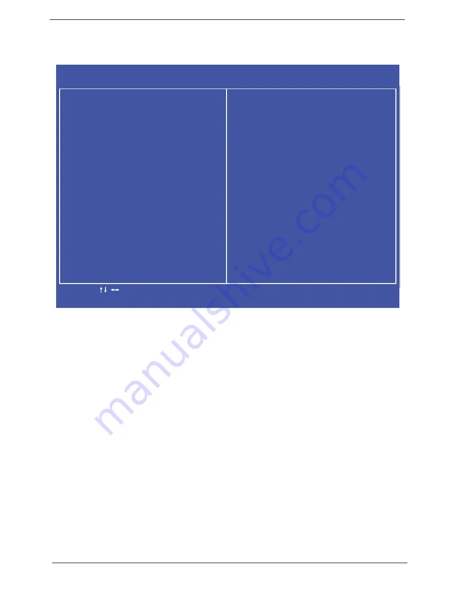
CMOS Setup Utility
The CMOS Setup Utility screen displays a list of the functions and features available in the BIOS.
Use the arrow keys to scroll to the required menu and press Enter.
C M O S S e t u p U t i l i t y - C o p y r i g h t ( C ) 1 9 8 5 - 2 0 1 0 , A m e r i c a n M e g a t r e n d s I n c .
P r o d u c t I n f o r m a t i o n
S t a n d a r d C M O S F e a t u r e s
A d v a n c e d B i o s F e a t u r e s
A d v a n c e d C h i p s e t F e a t u r e s
I n t e g r a t e d P e r i p h e r a l s
P o w e r M a n a g e m e n t F e a t u r e s
P C H e a l t h S t a t u s
F r e q u e n c y Vo l t a g e C o n t r o l
B I O S S e c u r i t y F e a t u r e s
L o a d D e f a u l t S e t t i n g s
S a v e a n d E x i t S e t u p
E x i t W i t h o u t S a v i n g
- / + / :
Va lu e
: M o v e
F 1 : G e n e r
a l H e l p
E n t e r : S e l e c t
F 1 0 : S a
v e
E S C : E x i t
F 9 : O p t i m i z e d D
e f a u l t s
Summary of Contents for Z5700 Series
Page 6: ...VI ...
Page 10: ...X Table of Contents ...
Page 32: ...22 Chapter 1 ...
Page 55: ...45 Chapter 3 5 Lift the Hinge Cover clear of the device ...
Page 64: ...Chapter 3 54 11 Lift the mainboard shielding away from the chassis ...
Page 67: ...57 Chapter 3 7 Remove the brackets from the HDD ...
Page 71: ...61 Chapter 3 7 Lift the touchscreen board away ...
Page 74: ...Chapter 3 64 4 Lift the audio board and cable away at an angle from the rear cover ...
Page 76: ...Chapter 3 66 4 Remove the ODD Eject Board ...
Page 82: ...Chapter 3 72 8 Remove the Inverter Board ...
Page 84: ...Chapter 3 74 4 Remove the Home Button Board from the chassis ...
Page 86: ...Chapter 3 76 4 Turn the Camera Module over 5 Disconnect the cable from the Camera Module ...
Page 88: ...Chapter 3 78 4 Lift the TV module away ...
Page 90: ...Chapter 3 80 4 Lift the WLAN module away ...
Page 100: ...Chapter 3 90 8 Unlock the LVDS cable 9 Remove the LVDS cable ...
Page 103: ...93 Chapter 3 14 Remove the thirteen 13 screws Step Size Quantity Screw Type Frame M2 5 4 13 ...
Page 109: ...99 Chapter 3 4 Remove the home button board from the bezel ...
Page 112: ...Chapter 3 102 4 Remove the USB board from the chassis ...
Page 141: ...131 Chapter 3 7 Apply the adhesive tape to secure the Inverter Board cable 1 ...
Page 163: ...153 Chapter 3 4 Slide the RAM Cover into place ...
Page 184: ...Chapter 4 174 ...
Page 198: ...Appendix A 188 Model Definition and Configuration Appendix A ...
Page 199: ...189 Appendix A ...
Page 201: ...191 Appendix B ...
Page 204: ...194 ...
Page 205: ...195 ...
Page 206: ...196 ...