


Chapter 2
29
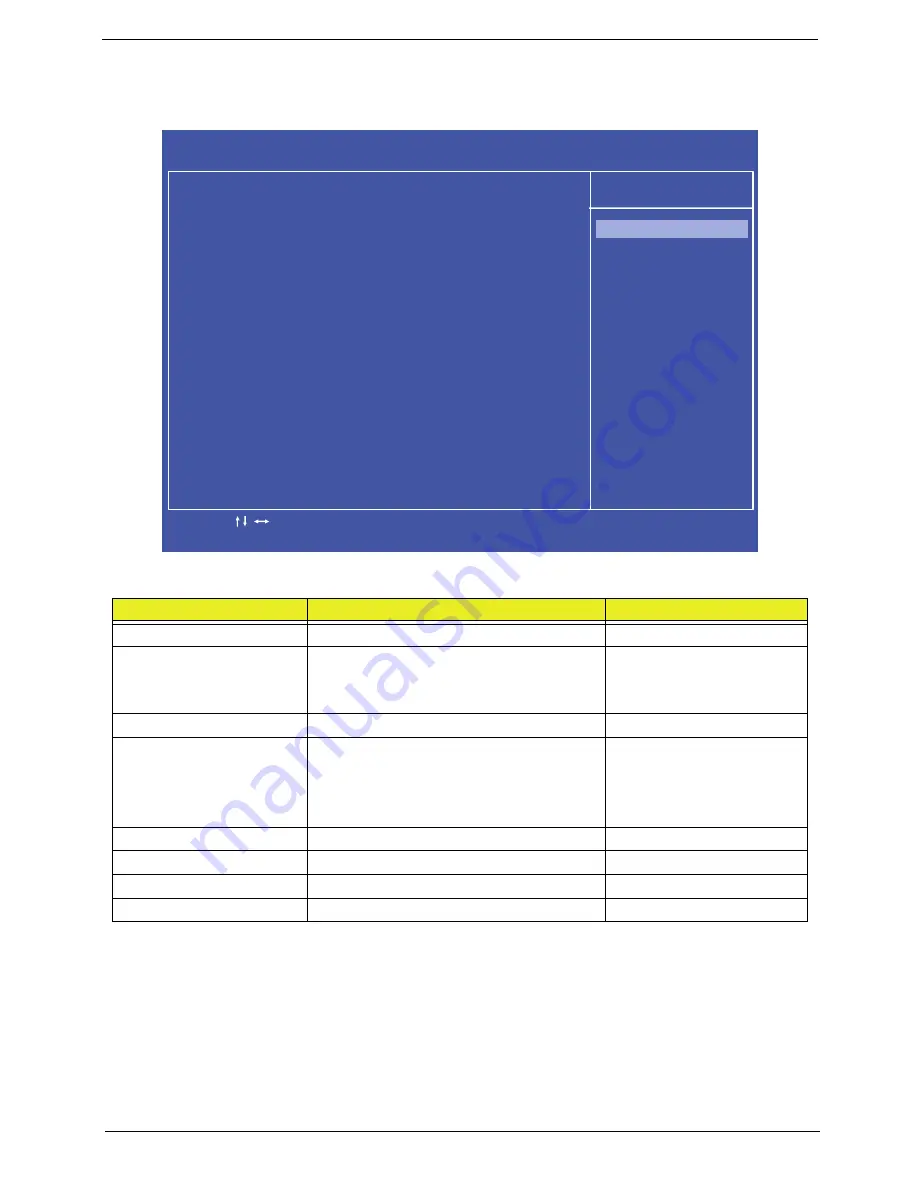
Integrated Peripherals
The Integrated Peripherals screen contains parameters for device peripherals.
The table below describes the items, menus, and submenus in this screen.
Parameter
Description
Format/Option
Onboard SATA Controller
Enable the SATA controller
Enabled
or Disabled
Onboard SATA Mode
Set the SATA mode
Options:
•
IDE
•
AHCI
Onboard USB Controller
Enable the USB controller.
Enabled
or Disabled
USB Storage Emulation
Set the USB storage emulation
Options:
•
Auto
•
Floppy
•
Hard Disk
Onboard Audio Controller
Enable or disable the audio controller
Enabled
or Disabled
Onboard LAN Controller
Enable or disable the LAN controller
Enabled
or Disabled
Onboard LAN Option ROM
Disable or enable LAN optional ROM
Disabled
or Enabled
Onboard CIR Controller
Enable or disable the CIR Controller
Enabled
or Disable
C M O S S e t u p U t i l i t y - C o p y r i g h t ( C ) 1 9 8 5 - 2 0 1 0 , A m e r i c a n M e g a t r e n d s I n c .
I n t e g r a t e d P e r i p h e r a l s
H e l p I t e m
O n b o a r d S ATA C o n t r o l l e r [ E n a b l e d ]
O n b o a r d S ATA M o d e [ A H C I ]
O n b o a r d U S B C o n t r o l l e r [ E n a b l e d ]
U S B S t o r a g e E m u l a t i o n [ A u t o ]
O n b o a r d A u d i o C o n t r o l l e r [ E n a b l e d ]
O n b o a r d L A N C o n t r o l l e r [ E n a b l e d ]
O n b o a r d L A N O p t i o n R O M [ D i s e n a b l e d ]
O n b o a r d C I R C o n t r o l l e r [ E n a b l e d ]
- / + / :
Va lu e
: M o v e
F 1 : G e n e r
a l H e l p
E n t e r : S e l e c t
F 1 0 : S a
v e
E S C : E x i t
F 9 : O p t i m i z e d D
e f a u l t s
O p t i o n s
D i s a b l e d
E n a b l e d
Summary of Contents for Z5700 Series
Page 6: ...VI ...
Page 10: ...X Table of Contents ...
Page 32: ...22 Chapter 1 ...
Page 55: ...45 Chapter 3 5 Lift the Hinge Cover clear of the device ...
Page 64: ...Chapter 3 54 11 Lift the mainboard shielding away from the chassis ...
Page 67: ...57 Chapter 3 7 Remove the brackets from the HDD ...
Page 71: ...61 Chapter 3 7 Lift the touchscreen board away ...
Page 74: ...Chapter 3 64 4 Lift the audio board and cable away at an angle from the rear cover ...
Page 76: ...Chapter 3 66 4 Remove the ODD Eject Board ...
Page 82: ...Chapter 3 72 8 Remove the Inverter Board ...
Page 84: ...Chapter 3 74 4 Remove the Home Button Board from the chassis ...
Page 86: ...Chapter 3 76 4 Turn the Camera Module over 5 Disconnect the cable from the Camera Module ...
Page 88: ...Chapter 3 78 4 Lift the TV module away ...
Page 90: ...Chapter 3 80 4 Lift the WLAN module away ...
Page 100: ...Chapter 3 90 8 Unlock the LVDS cable 9 Remove the LVDS cable ...
Page 103: ...93 Chapter 3 14 Remove the thirteen 13 screws Step Size Quantity Screw Type Frame M2 5 4 13 ...
Page 109: ...99 Chapter 3 4 Remove the home button board from the bezel ...
Page 112: ...Chapter 3 102 4 Remove the USB board from the chassis ...
Page 141: ...131 Chapter 3 7 Apply the adhesive tape to secure the Inverter Board cable 1 ...
Page 163: ...153 Chapter 3 4 Slide the RAM Cover into place ...
Page 184: ...Chapter 4 174 ...
Page 198: ...Appendix A 188 Model Definition and Configuration Appendix A ...
Page 199: ...189 Appendix A ...
Page 201: ...191 Appendix B ...
Page 204: ...194 ...
Page 205: ...195 ...
Page 206: ...196 ...