


26
Chapter 2
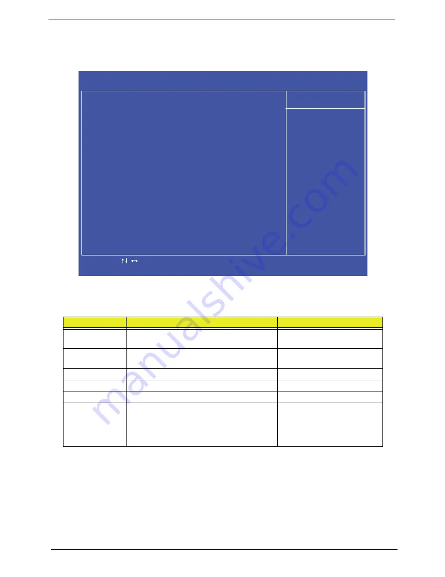
Standard CMOS Features
The Standard CMOS Features screen allows the user to set the system time and date as well as set HDD and
ODD options.
NOTE:
The screen above is for your reference only. Actual values may differ.
The table below describes the parameters in this screen. Settings in
boldface
are the default parameter
settings.
Parameter
Description
Format/Option
System Date
Sets the system date.
Format MM/DD/YYYY (month/
day/year)
System Time
Sets the system time. The hours are displayed
with 24-hour format.
Format: HH:MM:SS
(hour:minute:second)
SATA Port 1
SATA Port 2
AHCI Port 4
Halt On
Instructs the BIOS to halt during boot up for
the selected error parameter.
Options:
•
All Errors
•
No Errors
•
All, But keyboard
C M O S S e t u p U t i l i t y - C o p y r i g h t ( C ) 1 9 8 5 - 2 0 1 0 , A m e r i c a n M e g a t r e n d s I n c .
S t a n d a r d C M O S F e a t u r e s
H e l p I t e m
S y s t e m D a t e [ Tu e 0 4 / 2 5 / 2 0 1 0 ]
S y s t e m Ti m e [ 0 5 : 0 0 : 3 3 ]
A H C I P o r t 1
[ H a r d D i s k ]
A H C I P o r t 2
[ ATA P I C D R O M ]
A H C I P o r t 4
[ N o t D e t e c t e d ]
H a l t O n [ A l l , B u t K e y b o a r d ]
U s e [ E n t e r ] , [ TA B ]
o r [ S h i f t - TA B ] t o
s e l e c t a f i e l d .
U s e [ + ] o r [ - ] t o
c o n f i g u r e s y s t e m D a t e
- / + / :
Va lu e
: M o v e
F 1 : G e n e r
a l H e l p
E n t e r : S e l e c t
F 1 0 : S a
v e
E S C : E x i t
F 9 : O p t i m i z e d D
e f a u l t s
Summary of Contents for Z5700 Series
Page 6: ...VI ...
Page 10: ...X Table of Contents ...
Page 32: ...22 Chapter 1 ...
Page 55: ...45 Chapter 3 5 Lift the Hinge Cover clear of the device ...
Page 64: ...Chapter 3 54 11 Lift the mainboard shielding away from the chassis ...
Page 67: ...57 Chapter 3 7 Remove the brackets from the HDD ...
Page 71: ...61 Chapter 3 7 Lift the touchscreen board away ...
Page 74: ...Chapter 3 64 4 Lift the audio board and cable away at an angle from the rear cover ...
Page 76: ...Chapter 3 66 4 Remove the ODD Eject Board ...
Page 82: ...Chapter 3 72 8 Remove the Inverter Board ...
Page 84: ...Chapter 3 74 4 Remove the Home Button Board from the chassis ...
Page 86: ...Chapter 3 76 4 Turn the Camera Module over 5 Disconnect the cable from the Camera Module ...
Page 88: ...Chapter 3 78 4 Lift the TV module away ...
Page 90: ...Chapter 3 80 4 Lift the WLAN module away ...
Page 100: ...Chapter 3 90 8 Unlock the LVDS cable 9 Remove the LVDS cable ...
Page 103: ...93 Chapter 3 14 Remove the thirteen 13 screws Step Size Quantity Screw Type Frame M2 5 4 13 ...
Page 109: ...99 Chapter 3 4 Remove the home button board from the bezel ...
Page 112: ...Chapter 3 102 4 Remove the USB board from the chassis ...
Page 141: ...131 Chapter 3 7 Apply the adhesive tape to secure the Inverter Board cable 1 ...
Page 163: ...153 Chapter 3 4 Slide the RAM Cover into place ...
Page 184: ...Chapter 4 174 ...
Page 198: ...Appendix A 188 Model Definition and Configuration Appendix A ...
Page 199: ...189 Appendix A ...
Page 201: ...191 Appendix B ...
Page 204: ...194 ...
Page 205: ...195 ...
Page 206: ...196 ...