


182
Chapter 6
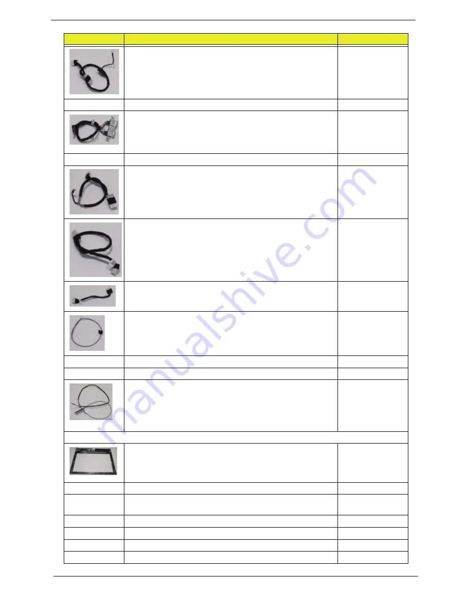
INVERTER CABLE
50.SDB07.008
LED CABLE
50.SCY07.009
USB CABLE W/PORT
50.SCY07.010
POWER CABLE
50.SCY07.011
CARD READER CABLE
50.SDB07.009
HOME BUTTON CABLE
50.SCY07.016
BLUETOOTH CABLE
50.SCY07.013
TV TUNER CABLE
50.SCY07.014
TV EXTERNAL ANTENNA - DVB-T
50.SCY07.017
TV EXTERNAL ANTENNA - ATSC
50.G8507.011
ANTENNA
50.SCY07.018
CASE/COVER/BRACKET ASSEMBLY
FRONT COVER ASSY SILVER W/SPEAKER,H/BUTTON
B,ANTENNA,USB PORT
60.SDB07.001
BACK COVER RED HDMI W/TV, IR, IR BLASKER, W/O B
CAS
60.SDB07.002
BACK COVER RED HDMI W/O TV, W/O B CAS
60.SDB07.003
BACK COVER RED HDMI W/TV, W/ B CAS
60.SDB07.004
BACK COVER RED HDMI W/O TV, W/ B CAS
60.SDB07.005
RAM COVER - RED
42.SCY07.001
CATEGORY
ACER DESCRIPTION
ACER PART NO.
Summary of Contents for Z5700 Series
Page 6: ...VI ...
Page 10: ...X Table of Contents ...
Page 32: ...22 Chapter 1 ...
Page 55: ...45 Chapter 3 5 Lift the Hinge Cover clear of the device ...
Page 64: ...Chapter 3 54 11 Lift the mainboard shielding away from the chassis ...
Page 67: ...57 Chapter 3 7 Remove the brackets from the HDD ...
Page 71: ...61 Chapter 3 7 Lift the touchscreen board away ...
Page 74: ...Chapter 3 64 4 Lift the audio board and cable away at an angle from the rear cover ...
Page 76: ...Chapter 3 66 4 Remove the ODD Eject Board ...
Page 82: ...Chapter 3 72 8 Remove the Inverter Board ...
Page 84: ...Chapter 3 74 4 Remove the Home Button Board from the chassis ...
Page 86: ...Chapter 3 76 4 Turn the Camera Module over 5 Disconnect the cable from the Camera Module ...
Page 88: ...Chapter 3 78 4 Lift the TV module away ...
Page 90: ...Chapter 3 80 4 Lift the WLAN module away ...
Page 100: ...Chapter 3 90 8 Unlock the LVDS cable 9 Remove the LVDS cable ...
Page 103: ...93 Chapter 3 14 Remove the thirteen 13 screws Step Size Quantity Screw Type Frame M2 5 4 13 ...
Page 109: ...99 Chapter 3 4 Remove the home button board from the bezel ...
Page 112: ...Chapter 3 102 4 Remove the USB board from the chassis ...
Page 141: ...131 Chapter 3 7 Apply the adhesive tape to secure the Inverter Board cable 1 ...
Page 163: ...153 Chapter 3 4 Slide the RAM Cover into place ...
Page 184: ...Chapter 4 174 ...
Page 198: ...Appendix A 188 Model Definition and Configuration Appendix A ...
Page 199: ...189 Appendix A ...
Page 201: ...191 Appendix B ...
Page 204: ...194 ...
Page 205: ...195 ...
Page 206: ...196 ...