


155
Chapter 4
ODD Failure
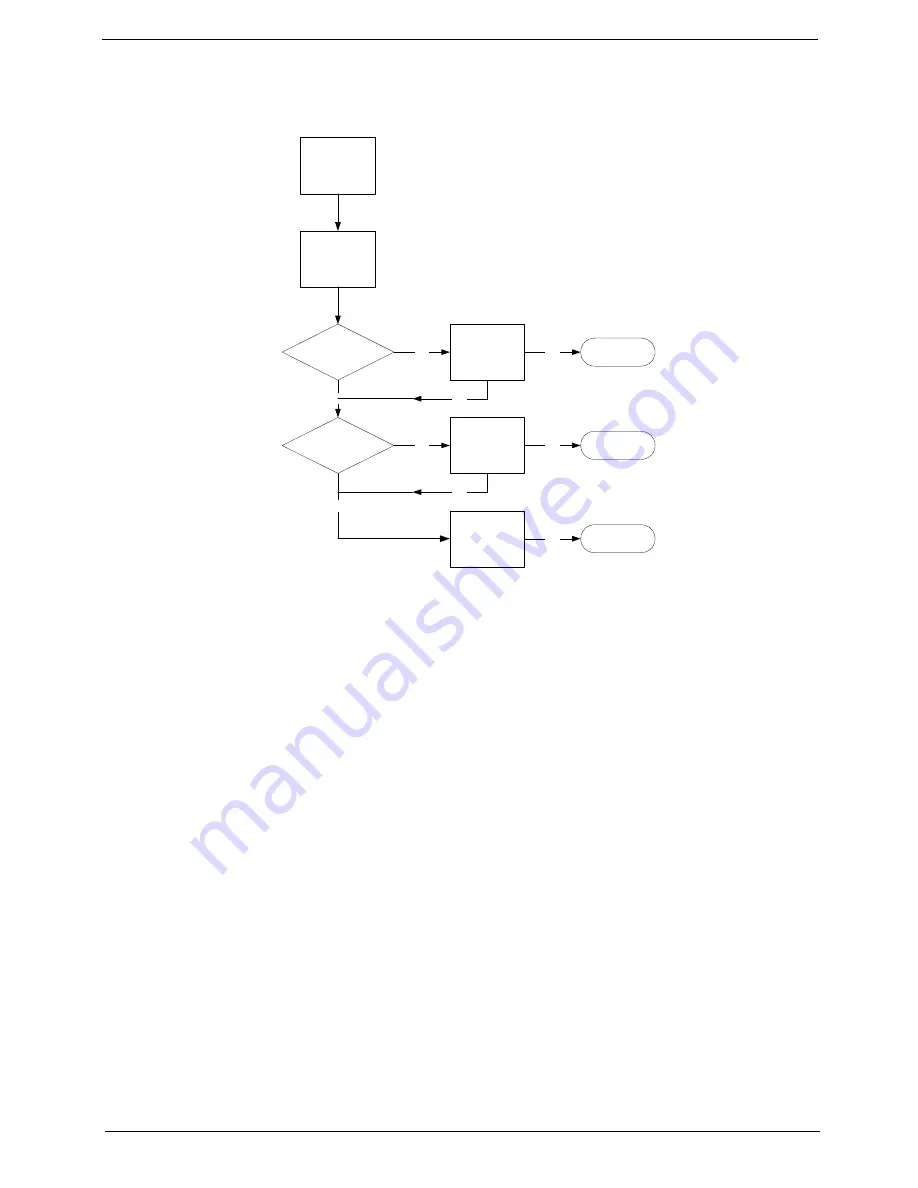
If an Optical Disk Drive failure is determined, use the following flowchart to determine the required action:
ODD Not Operating Correctly
If the
ODD
exhibits any of the following symptoms it may be faulty:
•
Audio CDs do not play when loaded
•
DVDs do not play when loaded
•
Blank discs do not burn correctly
•
DVD or CD play breaks up or jumps
•
Optical drive not found or not active:
•
Not shown in My Computer or the BIOS setup
•
LED does not flash when the computer starts up
•
The tray does not eject
•
Access failure screen displays
•
The ODD is noisy
Perform the following general solutions one at a time to correct the problem.
1.
Reboot the computer and retry the operation.
2.
Try an alternate disc.
3.
Navigate to
Start
Computer
. Check that the ODD device is displayed in the
Devices
with
Removable
Storage
panel.
4.
Navigate to
Start
Control
Panel
System
and
Maintenance
System
Device
Manager
.
a.
Double-click
lDE ATA/ATAPI controllers
. If a device displays a down arrow, right-click on the device
and click
Enable
.
START
Check DVD
cable connection
DVD does not
play
Reconnect
cable correctly
Check DVD
module
Replace ODD
module
Close
Close
Close
OK
NG
OK
OK
NG
NG
Replace
Mainboard
OK
NG
OK
Summary of Contents for Z5700 Series
Page 6: ...VI ...
Page 10: ...X Table of Contents ...
Page 32: ...22 Chapter 1 ...
Page 55: ...45 Chapter 3 5 Lift the Hinge Cover clear of the device ...
Page 64: ...Chapter 3 54 11 Lift the mainboard shielding away from the chassis ...
Page 67: ...57 Chapter 3 7 Remove the brackets from the HDD ...
Page 71: ...61 Chapter 3 7 Lift the touchscreen board away ...
Page 74: ...Chapter 3 64 4 Lift the audio board and cable away at an angle from the rear cover ...
Page 76: ...Chapter 3 66 4 Remove the ODD Eject Board ...
Page 82: ...Chapter 3 72 8 Remove the Inverter Board ...
Page 84: ...Chapter 3 74 4 Remove the Home Button Board from the chassis ...
Page 86: ...Chapter 3 76 4 Turn the Camera Module over 5 Disconnect the cable from the Camera Module ...
Page 88: ...Chapter 3 78 4 Lift the TV module away ...
Page 90: ...Chapter 3 80 4 Lift the WLAN module away ...
Page 100: ...Chapter 3 90 8 Unlock the LVDS cable 9 Remove the LVDS cable ...
Page 103: ...93 Chapter 3 14 Remove the thirteen 13 screws Step Size Quantity Screw Type Frame M2 5 4 13 ...
Page 109: ...99 Chapter 3 4 Remove the home button board from the bezel ...
Page 112: ...Chapter 3 102 4 Remove the USB board from the chassis ...
Page 141: ...131 Chapter 3 7 Apply the adhesive tape to secure the Inverter Board cable 1 ...
Page 163: ...153 Chapter 3 4 Slide the RAM Cover into place ...
Page 184: ...Chapter 4 174 ...
Page 198: ...Appendix A 188 Model Definition and Configuration Appendix A ...
Page 199: ...189 Appendix A ...
Page 201: ...191 Appendix B ...
Page 204: ...194 ...
Page 205: ...195 ...
Page 206: ...196 ...