


Chapter 1
11
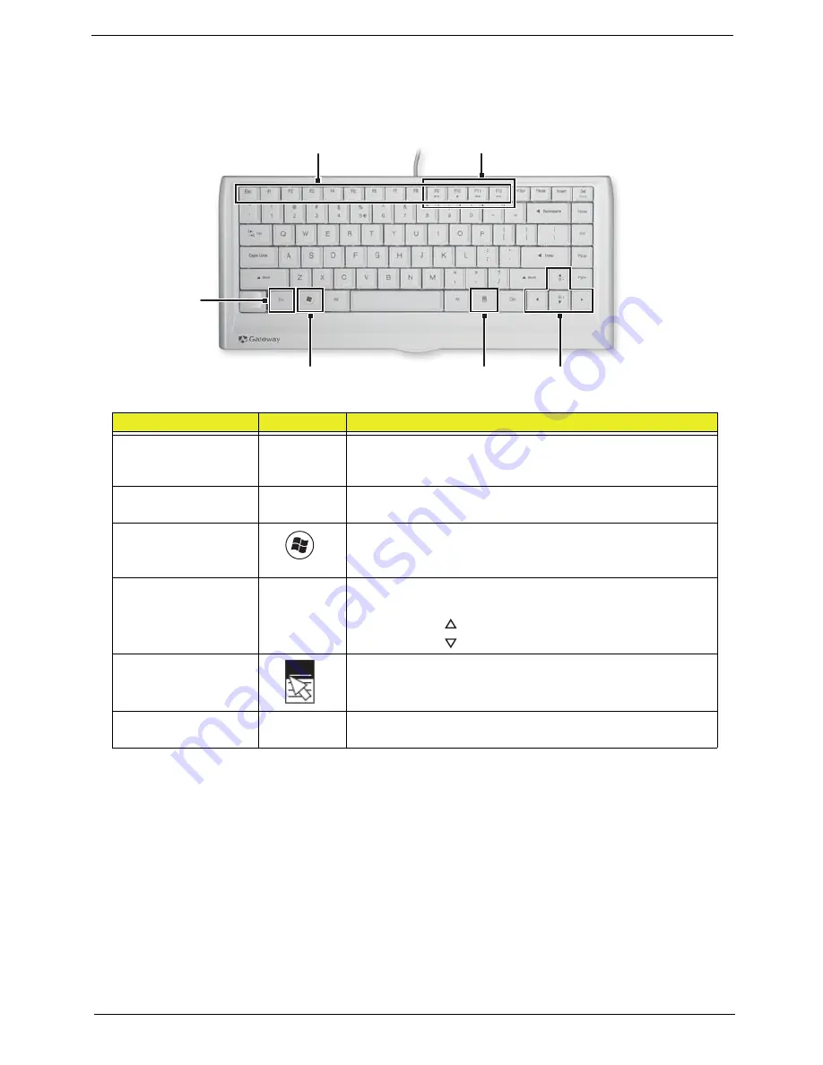
Using the Keyboard
The keyboard has several different types of keys and buttons as shown below.
Feature
Icon
Description
Function keys
Press these keys to start program actions. Each program uses
different function keys for different purposes. See the program
documentation to find out more about the function key actions.
Audio playback keys
Press these keys to play your audio files and to adjust the
volume.
Windows key
Press this key to open the Windows Start menu.
This key can also be used in combination with other keys to
open utilities. See “Windows Keys” on page 12.
Fn key
Press this key in combination with keys that have alternate
functions defined, such as the
F9
-
F12
keys.
Press <
Fn
> + <
> to increase the brightness of the display.
Press <
Fn
> + <
> to decrease the brightness of the display.
Application key
Press this key to access shortcut menus and help assistants in
Windows.
Navigation keys
Press these keys to move the cursor and to copy, cut, and
paste objects.
Windows key
Application
key
Navigation keys
Function keys
Audio playback keys
Fn key
Summary of Contents for Z5700 Series
Page 6: ...VI ...
Page 10: ...X Table of Contents ...
Page 32: ...22 Chapter 1 ...
Page 55: ...45 Chapter 3 5 Lift the Hinge Cover clear of the device ...
Page 64: ...Chapter 3 54 11 Lift the mainboard shielding away from the chassis ...
Page 67: ...57 Chapter 3 7 Remove the brackets from the HDD ...
Page 71: ...61 Chapter 3 7 Lift the touchscreen board away ...
Page 74: ...Chapter 3 64 4 Lift the audio board and cable away at an angle from the rear cover ...
Page 76: ...Chapter 3 66 4 Remove the ODD Eject Board ...
Page 82: ...Chapter 3 72 8 Remove the Inverter Board ...
Page 84: ...Chapter 3 74 4 Remove the Home Button Board from the chassis ...
Page 86: ...Chapter 3 76 4 Turn the Camera Module over 5 Disconnect the cable from the Camera Module ...
Page 88: ...Chapter 3 78 4 Lift the TV module away ...
Page 90: ...Chapter 3 80 4 Lift the WLAN module away ...
Page 100: ...Chapter 3 90 8 Unlock the LVDS cable 9 Remove the LVDS cable ...
Page 103: ...93 Chapter 3 14 Remove the thirteen 13 screws Step Size Quantity Screw Type Frame M2 5 4 13 ...
Page 109: ...99 Chapter 3 4 Remove the home button board from the bezel ...
Page 112: ...Chapter 3 102 4 Remove the USB board from the chassis ...
Page 141: ...131 Chapter 3 7 Apply the adhesive tape to secure the Inverter Board cable 1 ...
Page 163: ...153 Chapter 3 4 Slide the RAM Cover into place ...
Page 184: ...Chapter 4 174 ...
Page 198: ...Appendix A 188 Model Definition and Configuration Appendix A ...
Page 199: ...189 Appendix A ...
Page 201: ...191 Appendix B ...
Page 204: ...194 ...
Page 205: ...195 ...
Page 206: ...196 ...