


20
Chapter 1
Power Supply
RTC Battery
AC Adaptor
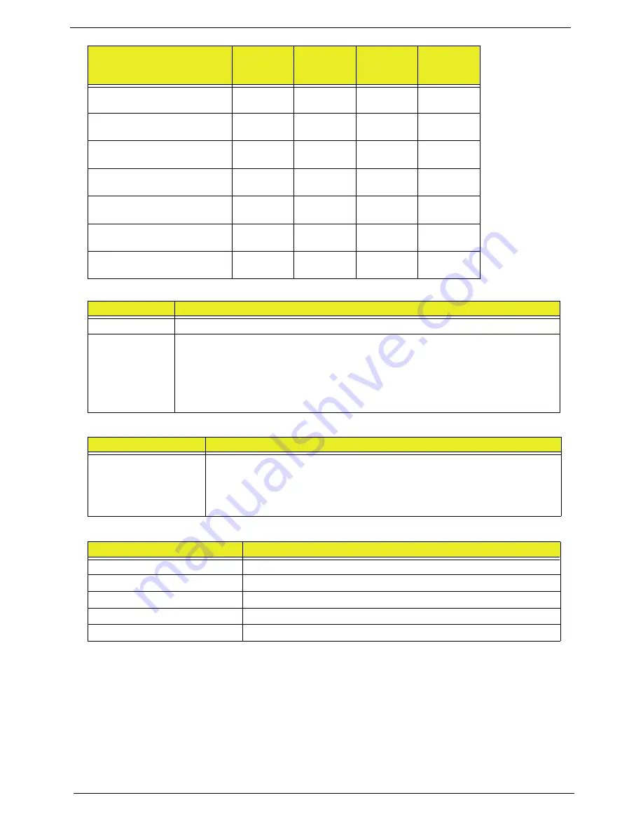
1366x768
Y
N
N
N
1400x900
Y
N
N
N
1400x1050
Y
N
N
N
1600x900
Y
N
Y
N
1600x1024
N
N
Y
N
1680x1050
Y
N
Y
N
1920x1080
Y
N
Y
N
Item
Specifications
AC Input
•
Auto ranging from 100V to 240V and 50Hz to 60Hz
DC Output
•
5V, 40W; 3.3V, 19.8W; 12V, 174W; 12V, 6W, 5VSB, 10W
•
Uses 3 prong ICE-320-C13 or IEC-320-C5 connector for AC power
•
Hold up time of 16ms under maximum load
•
Meet <1W Standby Energy Star requirement for Desktop Category B
•
Meet EU Lot 6 requirement
Item
Specifications
Lithium Rechargeable
Battery
•
Model: MIT CR2032
•
Voltage:2.5-3.0V
•
Capacity: 210mAh
•
Vendor: Mitsubishi
Item
Specification
Input rating
AC 100V - 240V, 50/60Hz
Output
19V 135W
Maximum input AC current
Inrush current
Efficiency
Resolution
24 bits
(UMA)
30 bits
36 bits
(Discrete)
48 bits
Summary of Contents for Z5700 Series
Page 6: ...VI ...
Page 10: ...X Table of Contents ...
Page 32: ...22 Chapter 1 ...
Page 55: ...45 Chapter 3 5 Lift the Hinge Cover clear of the device ...
Page 64: ...Chapter 3 54 11 Lift the mainboard shielding away from the chassis ...
Page 67: ...57 Chapter 3 7 Remove the brackets from the HDD ...
Page 71: ...61 Chapter 3 7 Lift the touchscreen board away ...
Page 74: ...Chapter 3 64 4 Lift the audio board and cable away at an angle from the rear cover ...
Page 76: ...Chapter 3 66 4 Remove the ODD Eject Board ...
Page 82: ...Chapter 3 72 8 Remove the Inverter Board ...
Page 84: ...Chapter 3 74 4 Remove the Home Button Board from the chassis ...
Page 86: ...Chapter 3 76 4 Turn the Camera Module over 5 Disconnect the cable from the Camera Module ...
Page 88: ...Chapter 3 78 4 Lift the TV module away ...
Page 90: ...Chapter 3 80 4 Lift the WLAN module away ...
Page 100: ...Chapter 3 90 8 Unlock the LVDS cable 9 Remove the LVDS cable ...
Page 103: ...93 Chapter 3 14 Remove the thirteen 13 screws Step Size Quantity Screw Type Frame M2 5 4 13 ...
Page 109: ...99 Chapter 3 4 Remove the home button board from the bezel ...
Page 112: ...Chapter 3 102 4 Remove the USB board from the chassis ...
Page 141: ...131 Chapter 3 7 Apply the adhesive tape to secure the Inverter Board cable 1 ...
Page 163: ...153 Chapter 3 4 Slide the RAM Cover into place ...
Page 184: ...Chapter 4 174 ...
Page 198: ...Appendix A 188 Model Definition and Configuration Appendix A ...
Page 199: ...189 Appendix A ...
Page 201: ...191 Appendix B ...
Page 204: ...194 ...
Page 205: ...195 ...
Page 206: ...196 ...