


Chapter 1
25
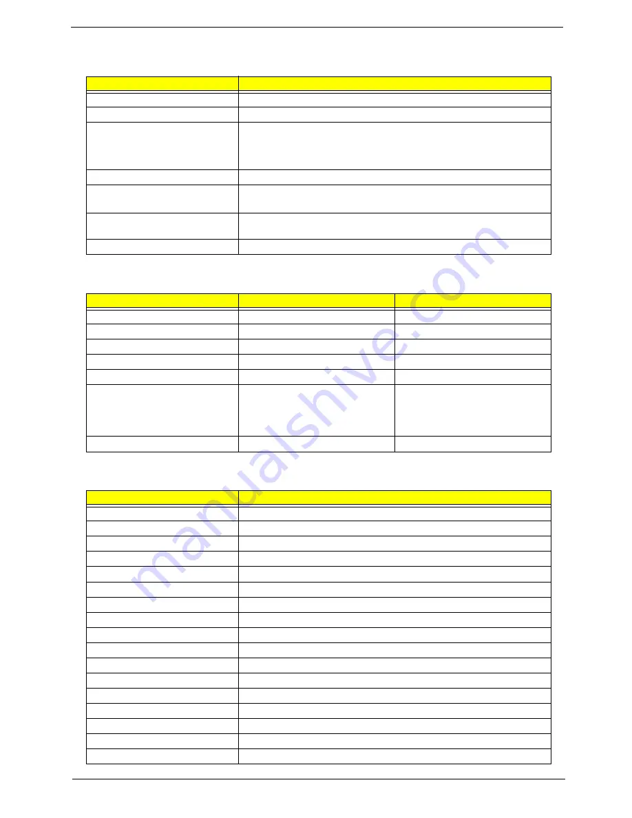
Mechanical Specifications
Item
Specification
Dimensions
308(W) x 247(D) x 24.5~29.9(H) mm for 14.1” TFT
Weight
5 lbs for 14.1” TFT model
I/O Ports
One type II PCMCIA (PC card) slot or one SmartBus slot, two USB ports, one
PS/2 keyboard/mouse port, one RJ11 port, one RJ45 port, one VGA port, on
line-out jack, one line-in/microphone-in jack, one 100-pin port-replicator
connector
Drive Bays
Two
Material
LCD panel & lower Case: Meg-Alloy
Others of housing: Plastic
Indicators
Wireless Communication, Power-on LED, Sleep, Media Activity, Battery Status,
Caps Lock, Num Lock
Switch
Power
Memory Address Map
Memory Addres
Size
Function
00000000-0009FFFF
640 KB
Base memory
000A0000-000BFFFF
128 KB
Video memory
000C0000-000CCFFF
48 KB
Video BIOS
000CA000-000CBFFF
8 KB
I/O ROM
000E0000-000FFFFF
128 KB
System BIOS
00100000-top limited
04301000-04301FFF
04302000-04302FFF
0430000-04300FFFF
--
4 KB
4 KB
64 KB
Extended (DIMM) memory
PCMCIA controller (slot 1)
PCMCIA controller (slot 2)
USB controller
FFFF0000-FFFFFFFF
64 KB
System board extension for PnP BIOS
I/O Address Map
I/O Address
Function
000-00F
DMA controller-1
020-021
Interrupt controller-1
040-043
Timer 1
060, 064
Keyboard controller 8742 chip select
062, 066
System speaker, ACPI embedded controller
061
System speaker
070-073
System CMOS/real-time clock
081-08F
DMA page register
0A0-0A1
Interrupt controller-2
0C0-0DF
DMA controller-2
0F0-0FE
Numeric data processor
170-177
2nd EIDE device (CD-ROM) select
1F0-1F7
1st EIDE device (hard drive) select
3F8-3FF
COM1
2F8-2FF
COM1or FIR (optional)
3E8-3EF
COM1or FIR (optional)
2E8-2EF
COM1or FIR (optional)
Summary of Contents for TravelMate 610 series
Page 6: ...VI ...
Page 10: ...VIII Table of Contents ...
Page 54: ...46 Chapter 2 ...
Page 61: ...Chapter 3 53 4 Disconnect the connector from the hard disk drive module ...
Page 71: ...Chapter 3 63 9 Then remove the two LCD hinges from the LCD panel ...
Page 82: ...74 Chapter 3 ...
Page 96: ...88 ...
Page 102: ...94 Chapter 5 ...
Page 104: ...96 ...
Page 114: ...106 ...
Page 116: ...108 Appendix A ...
Page 126: ...118 Appendix B ...
Page 128: ...120 Appendix C ...
Page 132: ...124 Index ...