28
Chapter 2
Information
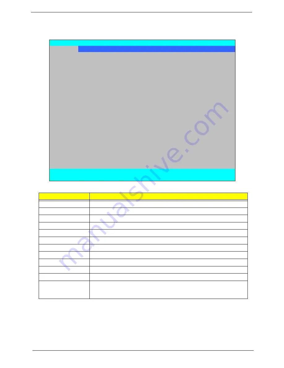
The Information screen displays a summary of your computer hardware information.
NOTE:
The system information is subject to different models.
Parameter
Description
CPU Type
This field shows the CPU type and speed of the system.
CPU Speed
This field shows the speed of the CPU.
HDD Model Name
This field shows the model name of HDD installed on primary IDE master.
HDD Serial Number
This field displays the serial number of HDD installed on primary IDE master.
ATAPI Model Name
This field shows the model name of the Optical device installed in the system.
System BIOS Version
Displays system BIOS version (MP models display BIOS ver. 1.01).
VGA BIOS Version
This field displays the VGA firmware version of the system.
Serial Number
This field displays the serial number of this unit.
Asset Tag Number
This field displays the asset tag number of the system.
Product Name
This field shows product name of the system.
Manufacturer Name
This field displays the manufacturer of this system.
UUID Number
Universally Unique Identifier (UUID) is an identifier standard used in software
construction, standardized by the Open Software Foundation (OSF) as part of
the Distributed Computing Environment (DCE).
PhoenixBIOS Setup Utility
Information
Main Advanced
Security
Power
Boot
AMD
Exit
CPU Type:
AMD Turion (tm) X2 Ultra Dual-Core Mobile ZM-84
CPU Speed:
2300 MHz
HDD Model Name:
Hitachi HTS542525K9SA00 -(PM)
HDD Serial Number:
071110BB0F00WDGS1K4C
ATAPI Model Name:
Slimtype DVD A DS8A2S -(PS)
System BIOS Version:
V1.01
VGA BIOS Version:
V010.080.000.000.027965
Serial Number:
Asset Tag Number:
Product Name:
Manufacturer Name:
UUID:
33643636336236356663001B38E109DB
F1
Help
↑↓
Select Item
F5/F6
Change Item
F9
Setup Default
ESC
Exit
←→
Select Menu
Enter
Select
(
Submenu
F10
Save and Exit
Summary of Contents for Aspire 5530 Series
Page 6: ...VI ...
Page 14: ...4 Chapter 1 System Block Diagram ...
Page 36: ...26 Chapter 1 ...
Page 62: ...52 Chapter 3 6 Remove the HDD cover as shown 7 Remove the WLAN cover as shown ...
Page 83: ...Chapter 3 73 6 Turn the upper cover over The upper cover appears as follows ...
Page 104: ...94 Chapter 3 7 Lift the Thermal Module clear of the Mainboard ...
Page 110: ...100 Chapter 3 6 Disconnect the left and right Inverter board cables as shown ...
Page 124: ...114 Chapter 3 3 Replace the RJ 11 cable in its housing ...
Page 135: ...Chapter 3 125 2 Replace the bracket as shown 3 Replace the single securing screw ...
Page 138: ...128 Chapter 3 2 Connect the seven cables on the mainboard as shown B C D E F G A ...
Page 150: ...140 Chapter 3 ...
Page 178: ...168 Chapter 5 ...
Page 193: ...Chapter 6 183 ...
Page 196: ...Appendix A 186 ...
Page 202: ...192 Appendix B ...
Page 204: ...194 Appendix C ...
Page 207: ...197 Windows 2000 Environment Test 188 Wireless Function Failure 154 WLAN Board 54 ...
Page 208: ...198 ...


