Chapter 1
7
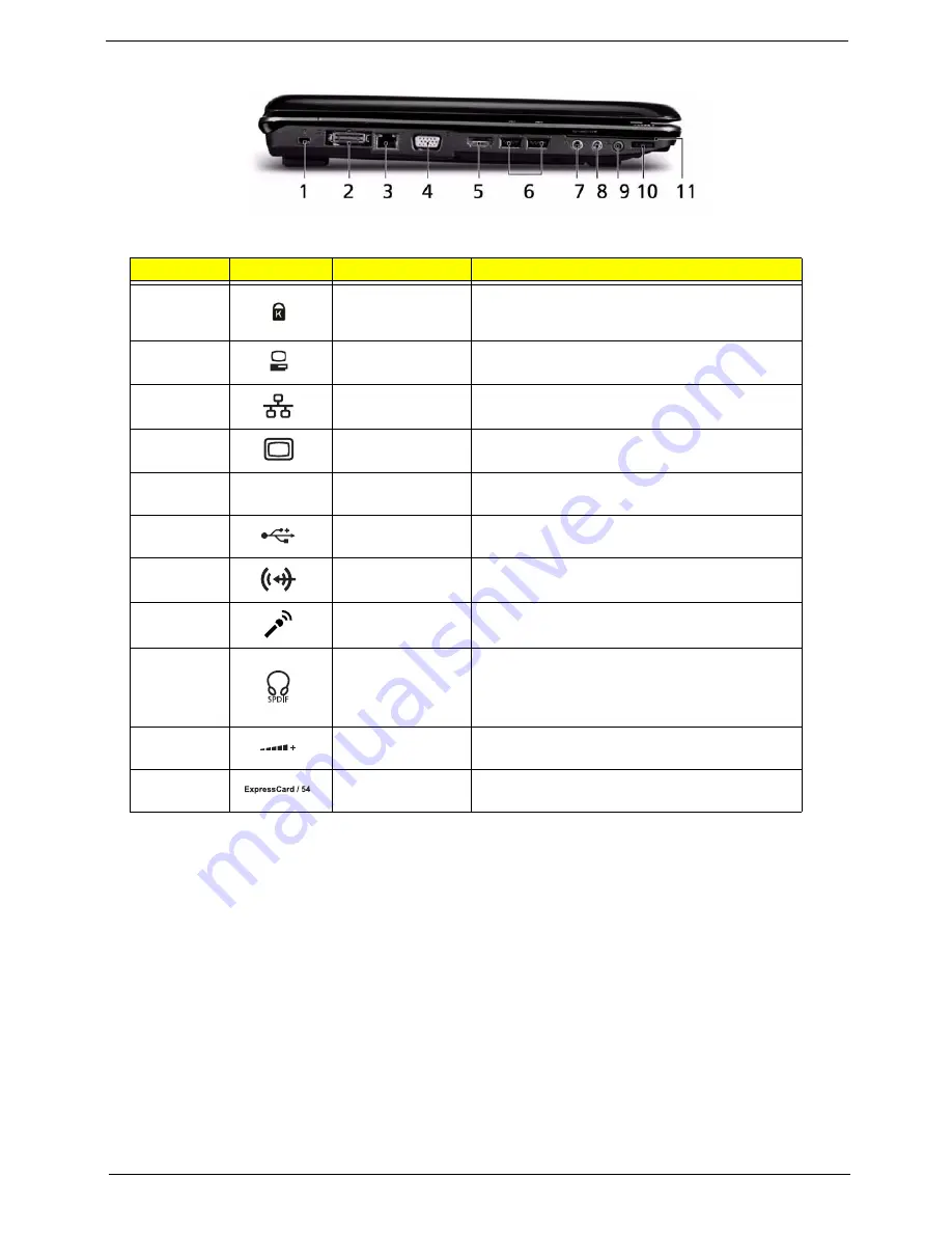
Left View
No.
Icon
Item
Description
1
Kensington lock
slot
Connects to a Kensington-compatible
computer security lock.
2
Acer EasyPort IV
connector
Connects to Acer EasyPort IV.
3
Ethernet (RJ-45)
port
Connects to an Ethernet 10/100/1000-based
network.
4
External display
(VGA) port
Connects to a display device
(e.g. external monitor, LCD projector).
5
HDMI
HDMI
Connects to a television or display device with
HDMI input.
6
2 USB 2.0 ports
Connect to USB 2.0 devices (e.g. USB mouse,
USB camera).
7
Line-in jack
Accepts audio line-in devices (e.g. audio CD
player, stereo walkman).
8
Microphone-in
jack
Accepts input from external microphones.
9
Headphones/
speaker/line-out
jack with S/PDIF
support
Connects to audio line-out devices
(e.g. speakers, headphones).
10
Unlimited volume
control wheel
Adjust the volume of the audio-out.
11
ExpressCard/54
slot
Accepts one ExpressCard/54 module.
Summary of Contents for Aspire 5530 Series
Page 6: ...VI ...
Page 14: ...4 Chapter 1 System Block Diagram ...
Page 36: ...26 Chapter 1 ...
Page 62: ...52 Chapter 3 6 Remove the HDD cover as shown 7 Remove the WLAN cover as shown ...
Page 83: ...Chapter 3 73 6 Turn the upper cover over The upper cover appears as follows ...
Page 104: ...94 Chapter 3 7 Lift the Thermal Module clear of the Mainboard ...
Page 110: ...100 Chapter 3 6 Disconnect the left and right Inverter board cables as shown ...
Page 124: ...114 Chapter 3 3 Replace the RJ 11 cable in its housing ...
Page 135: ...Chapter 3 125 2 Replace the bracket as shown 3 Replace the single securing screw ...
Page 138: ...128 Chapter 3 2 Connect the seven cables on the mainboard as shown B C D E F G A ...
Page 150: ...140 Chapter 3 ...
Page 178: ...168 Chapter 5 ...
Page 193: ...Chapter 6 183 ...
Page 196: ...Appendix A 186 ...
Page 202: ...192 Appendix B ...
Page 204: ...194 Appendix C ...
Page 207: ...197 Windows 2000 Environment Test 188 Wireless Function Failure 154 WLAN Board 54 ...
Page 208: ...198 ...


