ACE RC sky tech TS6i+ Instruction Manual Download Page 6

Page 10

Page 9

This switch does more than just turn the radio on and off-it also gets you into the initial setup programs when you hold down the two "EDIT" 
buttons as you slide the switch from "off" to "on".

When you turn off the switch after making selections in the initial setup menu, you "lock" your choices into the radio for this particular model 
slot. The switch is coupled to the light located a couple of inches above it-it comes on when the switch comes on and goes off when the 
switch is turned. 

This pair of buttons has three basic functions: they get you into the initial setup menu when you hold both EDIT buttons down and then turn 
on the radio; they get you into the model setup menu when you push both down when the radio is already on; and once you are in either of 
these menus pushing one button scrolls you up or down through the list of menu items. 

"EDIT"  buttons

When you are in a particular menu item, you'll use these two buttons to scroll within it-most commonly to the right or left to select a servo 
channel. When not in the programming mode, these buttons start, stop and reset the radio's countdown timer.

"CURSOR" buttons

As the "+" and "-" symbols imply, these buttons allow you to change a numerical value (most often a % value of servo travel) up or down 
within a menu item. When not in the programming mode either of these buttons enable the countdown timer. 

"DATA" buttons

This button is primarily a safety feature for powered models: When you push this button down the throttle channel on the model is taken 
off-line so that an accidental movement of the throttle stick won't change the setting. Get in the habit of using this function whenever you are 
carrying your model to the flight line. 

"LOCK" button

You can use the clear button whenever you want to reset a numerical value to its starting point. It is also used in one of the menu screens 
(the P MIX TRM) to turn a function on or off.

"CLEAR" button

On-Off Switch

Programming Switches and Buttons

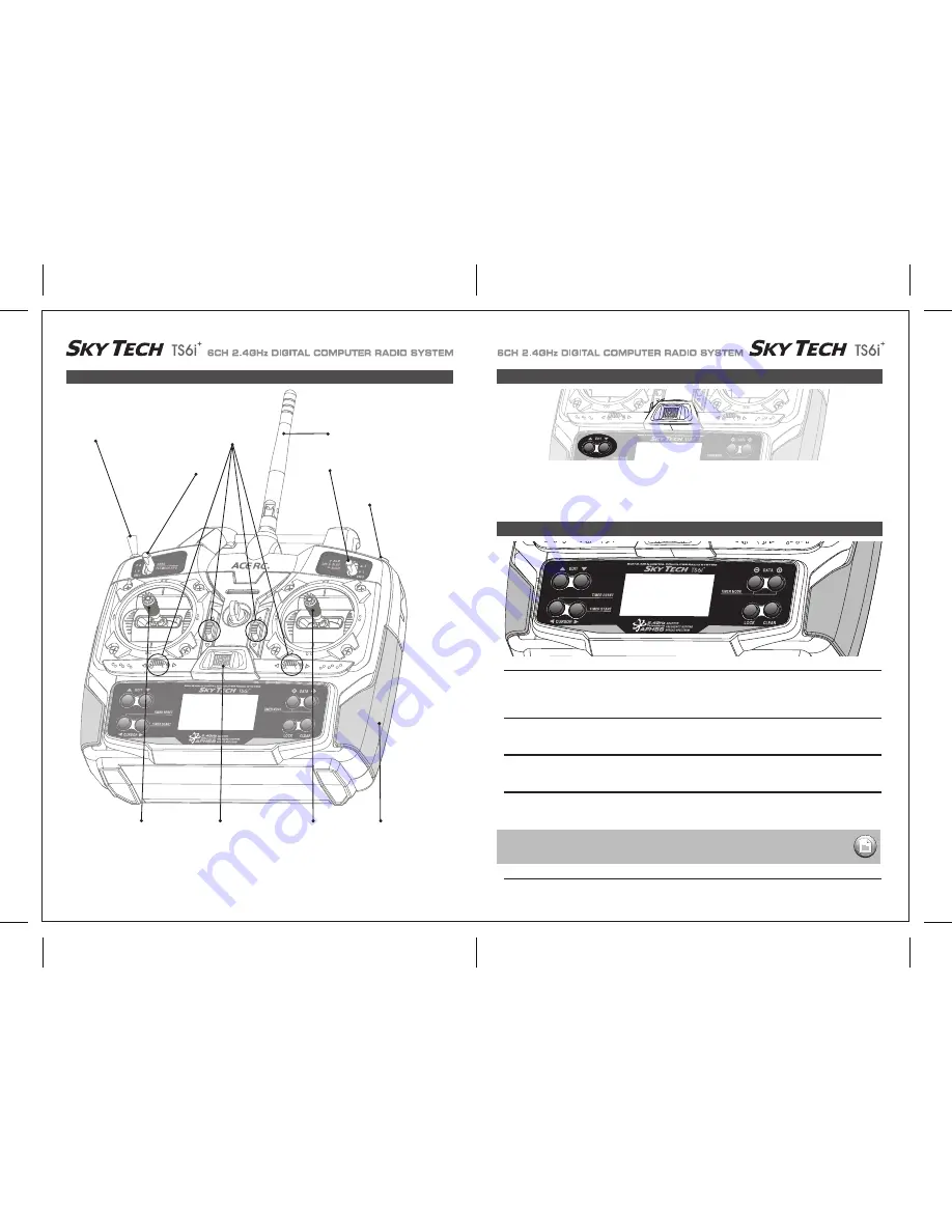
This figure shows the assignments for a Mode 2 system.
Note that some of the functions will not operate until activated in the mixing menus.

POWER

Trainer/Engine Cut Switch

SW 3

SW 1

Rudder & 

Throttle Stick

Aileron &

Elevator Stick

Plastic Side Panel

SW 2 

Antenna

Trim Switch

Power Switch

Control and Switch Assignments

POWER

POWER

SAFETY NOTE 

KEEP YOUR HANDS AWAY FROM THE PROPELLER OR ROTORS EVEN AFTER ENABLING THE LOCK 
FUNCTION-A RADIO GLITCH COULD STILL ACTIVATE THE THROTTLE !

Summary of Contents for sky tech TS6i+

Page 1: ...TEM 6CH 2 4GHz DIGITAL COMPUTER RADIO SYSTEM 6CH 2 4GHz DIGITAL COMPUTER RADIO SYSTEM Function Assignable Switches Easy to Read LCD Screen Built in ACE RC AFHSS 2 4GHz System 0678 INSTRUCTION MANUAL V...

Page 2: ...ion of this radio is that your models require six or less control channels If Sky Tech TS6i is your first programmable radio control transmitter you re probably feeling a bit overwhelmed by all the bu...

Page 3: ...r the servo rails the rubber grommets will not be able to attenuate vibration which can lead to mechanical wear and possible servo failure The Sky Tech TS6i can be used with most of the ACE RC s exist...

Page 4: ...he control sticks and trims alone then moving the control sticks 4 The instructor s transmitter has normal control over the model unless the trainer button is pressed passing control to the student s...

Page 5: ...amage or injury to anyone nearby Finally don t fly in the rain Water or moisture may enter the transmitter through the antenna or stick openings and cause erratic operation or loss of control Before y...

Page 6: ...timer CURSOR buttons As the and symbols imply these buttons allow you to change a numerical value most often a value of servo travel up or down within a menu item When not in the programming mode eith...

Page 7: ...AFHSS 2 4GHz System The TRS603DD is loaded with a variety of functions that are sure to deliver a satisfying R C experience The TRS603DD receiver is offered as a standard receiver for the Sky Tech TS...

Page 8: ...ed to use a large capacity BEC when a number of high torque servos are used and power requirements exceed that which the ESC provides Turning Off Turn off the receiver then turn off the transmitter Tu...

Page 9: ...moving properly do not fly the aircraft until the problem is solved Range Check Do a complete range check as described on page 21 before each flying session to confirm the radio system is working prop...

Page 10: ...signal radios 2 4GHz systems use a fixed shorter stubby transmitter antenna so the traditional method of range checking your system by lowering the transmitter antenna will not work We instead use a...

Page 11: ...lap Collective or Left Aileron FLPN on or Swash Servo 3 120 Startup Screen Lock Indicator Screen Timer When the battery s voltage drops to 6 6 volts this number starts blinking on the screen and the t...

Page 12: ...hand EDIT button to move to the next menu screen 2 Select the Model type programming baseline If you selected HELI as your model type this screen will appear allowing you to select between NORMAL 90...

Page 13: ...old which mode is currently active Now push down both EDIT buttons at the same time The following menu items will appear as you scroll down the list by pushing down the right hand EDIT button POWER Tr...

Page 14: ...setting procedure for left rudder Rudder End Points In the same manner as described above set EPA values for channel 5 landing gear or flaps if your model has these functions Flap or Landing Gear End...

Page 15: ...e or course for all the parameters we are going to establish in this menu set D R Dual Rate Press the Right Cursor key one time to get Channel 2 blinking With the switch in the 1 position set the elev...

Page 16: ...move over to CH 2 and push both DATA buttons simultaneously You ll notice that the symbol NOR ahead of CH has changed to REV and that the servo is now operating as it should on your model If any othe...

Page 17: ...s are stalling at their maximum throw turn down the value in the EPA screen or move the pushrod further up on the aileron horn to physically reduce the throw This is another built in mixing program av...

Page 18: ...Eng Cut button located on the upper right hand corner of the transmitter case CUT Engine Cut Function This program allows you to initiate a mixing of the ailerons ith flaps or Flaperon to camber the...

Page 19: ...exponential settings in addition to those established with the switch SW 3 in the center normal NOR position We ll assume that you have already activated modes ST1 and ST2 on this switch as instructed...

Page 20: ...Combined Flaps Ailerons 34 FLT C Flight Condition NOR ST1 ST2 ST3 If this is your first Sailplane If this is your first model Sailplane here are a few tips that will streamline your experience in prog...

Page 21: ...ction usually about twice as much UP movement as DOWN is an especially important quality for sailplanes as differential reduces the parasitic drag due to a yawing fuselage and unnecessary aileron trav...

Page 22: ...the elevator will move down very slightly relative to its normal angle of incidence This allows the glider to quickly fly between thermals and through areas of sink Thermal With the SW 3 switch pushed...

Page 23: ...plate type 120 is also referred to as SN 3 Heli SwashPlate POWER Trainer Engine Cut Switch SW 3 SW 1 Rudder Throttle Stick Aileron Elevator Stick Plastic Side Panel SW 2 Antenna Trim Switch Power Swit...

Page 24: ...ntrol the RPM of the motor The Speed Control may have settings that need to be programmed so check the Speed Controller manual 2 In smaller electric heli s a large motor battery provides the power for...

Page 25: ...dy for making the control less sensitive there P CV Pitch Curve 1 Press one of the Up Down EDIT buttons until the P CV window appears The default is for a linear curve a straight line from 0 to 100 pa...

Page 26: ...de SW 3 switch all the way back NOR will be flashing on and off Set the percentage to yield the desired gyro gain this is usually a high gain setting If for some reason you want a 0 setting press the...

Page 27: ...up the swash screen by repeatedly pressing one of the Up Down EDIT buttons until the SWAH window appears The function is automatically active when you select 120 mixing in the model setup menu 5 If al...

Page 28: ...L U L U L U R D R D R D R D R D R D MAS SLV ON OFF STICK SERVO STICK SERVO ON INH STICK SERVO ON INH NOR ST1 ST2 ST3 ON ON OFF ON OFF ON OFF 1 2 AILE CH1 AILE CH5 ON INH ON INH ON INH NOR ST1 ST2 ST3...

Reviews: