


Page 26
Page 25
EPA (End Point Adjustment)
EPA (End Point Adjustment)
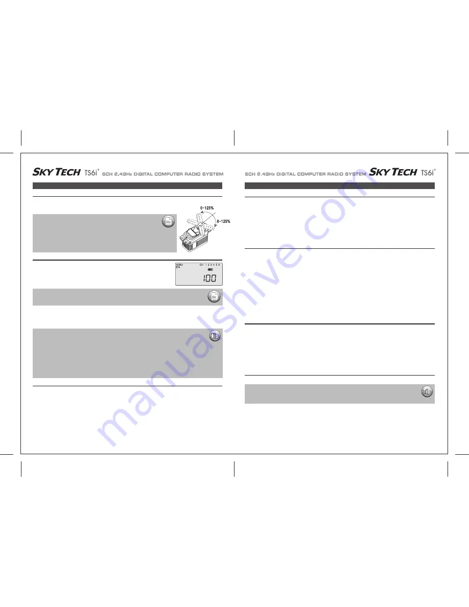
The EPA function is used to set (or limit) the travel of each servo, and may be set anywhere from 0% and 125%
for each travel direction. Reducing the percentage settings reduces the total servo throw in that direction. The
EPA function is normally used to prevent any servos from binding at the ends of their travel.
When you first enter the EPA menu, you'll see the default screen as shown.
The CH (channel) "1" right aileron is flashing and the travel value sits at 100%. Notice that you can change the R/D indicator symbol above
the value to L/U by moving the stick to the left.
You are about to see how this allows you set the travel directions independently for each stick motion.
1) To set the RIGHT TURN aileron motion (which is upward on the right wing and downward on the left wing), move the aileron stick all the
way to the right and hold it.
The right wing's aileron should move upward and the letters "R/D" should appear above the percent value, meaning you are setting "R"
for Right aileron turn.
2) If your servo is stalled or binding, you'll hear a buzzing sound. Hit the minus “
ㅡ
” DATA button until the buzzing stops.
If the servo is not buzzing, leave the setting at 100%. If you can, choose a location for the pushrod on the servo arm so that the throw is
adjusted in the 90-100% range.
3) To set the maximum travel of the LEFT (downward) motion, move the aileron stick all the way to the left and hold it. The letters "L/U"
should appear above the percent sign (as shown in the figure above). ("L" is for Left aileron turn).
Again listen and hit the -Decrease DATA button until the buzzing stops.
If the servo is not buzzing, apply the same value as you did for the right turn setting.
EPA (End Point Adjustment)
1) To set the UP elevator motion, press on the Right CURSOR button until CH "2" is flashing.
Now move the right stick all the way toward the transmitter bottom and hold it. The letters "L/U" should appear above the percentage value.
(Indicating you are setting "U", the UPWARD motion of the elevator-which also happens to be the upward movement of the control surface.
Again listen for a buzzing sound to indicate that the servo is stalling, and hit the “
ㅡ
” DATA button until the buzzing stops.
If the servo is not buzzing, leave the setting at 100%.
2) Repeat the previous step to set the DOWN elevator by moving the stick all the way toward the top of the transmitter (R/D will light up).
While the elevator is in full down position, check for binding and buzzing and reduce the travel value as necessary.
Elevator End Points
1) To set the RIGHT rudder motion, press the Right CURSOR button until the indicator moves over channel 4.
Now move the left stick all the way to the right and hold it.
The letters "R/D" should appear above the percentage value.
Listen for a buzzing sound to indicate the rudder servo is stalling, and hit the “
ㅡ
” DATA button until the buzzing stops.
If the servo is not buzzing, leave the setting at 100%.
You may wish to increase or decrease this number depending on how strongly the model reacts when the rudder is deflected.
2) Now move the stick to the left side, and repeat the setting procedure for left rudder.
Rudder End Points
In the same manner as described above, set EPA values for channel 5 (landing gear or flaps) if your model has these functions.
Flap (or Landing Gear) End Points
1) To set the throttle position at IDLE, first return to the regular display (push both DATA buttons) and push the trim button to the right of
left-hand joystick to set the throttle trim to read 0% on the screen.
2) Then go back to the EPA menu and press the Right CURSOR button until channel number 3 is blinking.
Now move the throttle stick all the way to the transmitter bottom and hold it. The letters "L/U" should appear next to the flashing percent sign.
Push the -Decrease DATA button until the servo moves the throttle plate to a nearly - but not completely - closed engine idle position.
If necessary when testing the motor, you may increase or decrease the travel of the servo at idle so you can't accidentally shut off the
engine using the trim tab.
3) To set the FULL throttle position, move the throttle stick all the way to the transmitter top and hold it.
The letters "R/D" should appear next to the flashing percent sign.
Listen for a buzzing sound to indicate the servo is stalling, and hit the “
ㅡ
” DATA button until the buzzing stops.
If the servo is not buzzing, leave the setting at 100% or change your linkage as necessary to fully open the throttle.
Throttle End Points
In this menu function you can set aileron up and down travel, up and down elevator travels,
right and left rudder travels, open and closed throttle positions, and aileron up and down
travelsif you have a second servo for the left wing.
You can also set the end point travel of flaps and landing gear.
Setting up End Points
Aileron End Points for Aircraft with one Aileron Servo
We recommend that before setting end points you first confirm the direction
of travel for the servo and reverse it if necessary using the servo reverse
function as noted on page 29.
Then center all the control surfaces as closely as possible by adjusting the pushrods or
other mechanical linkages between the servos and the horns on the control surfaces.
Then fine-tune the centering in the sub trim (S TRM) function screen as noted on page 29.
NOTE:
If you change the EPA setting to 0%, you will not have any servo response in that direction, and will
probably crash.
NOTE:
The following instructions to set aileron end points is based on an airplane using one aileron servo for both
ailerons. This servo would be plugged into the #1 channel of the receiver.
IF your airplane uses two aileron servos, one for each aileron, and you are in the ACRO mode, do the
following: Plug the right wing servo into ch. 1 and the left wing servo into ch. 6. Activate the Flaperon mix as shown
on page 31. Adjust the servo's direction of travel and end points as necessary.
IF your airplane uses two aileron servos, one for each aileron, and you are in GLID mode plug the right wing aileron
servo into ch. 1 and the left wing aileron servo into ch. 5. Activate the ADIF, or aileron differential function as shown
shown on page 40. Adjust the servo's direction of travel and end points as necessary.
Flight control surface travel should be published in the manual for your specific model.
Many model manufacturers will often publish two values, one for full rates, and one for a diminished
dual rates settings.


