


Page 20
Page 19
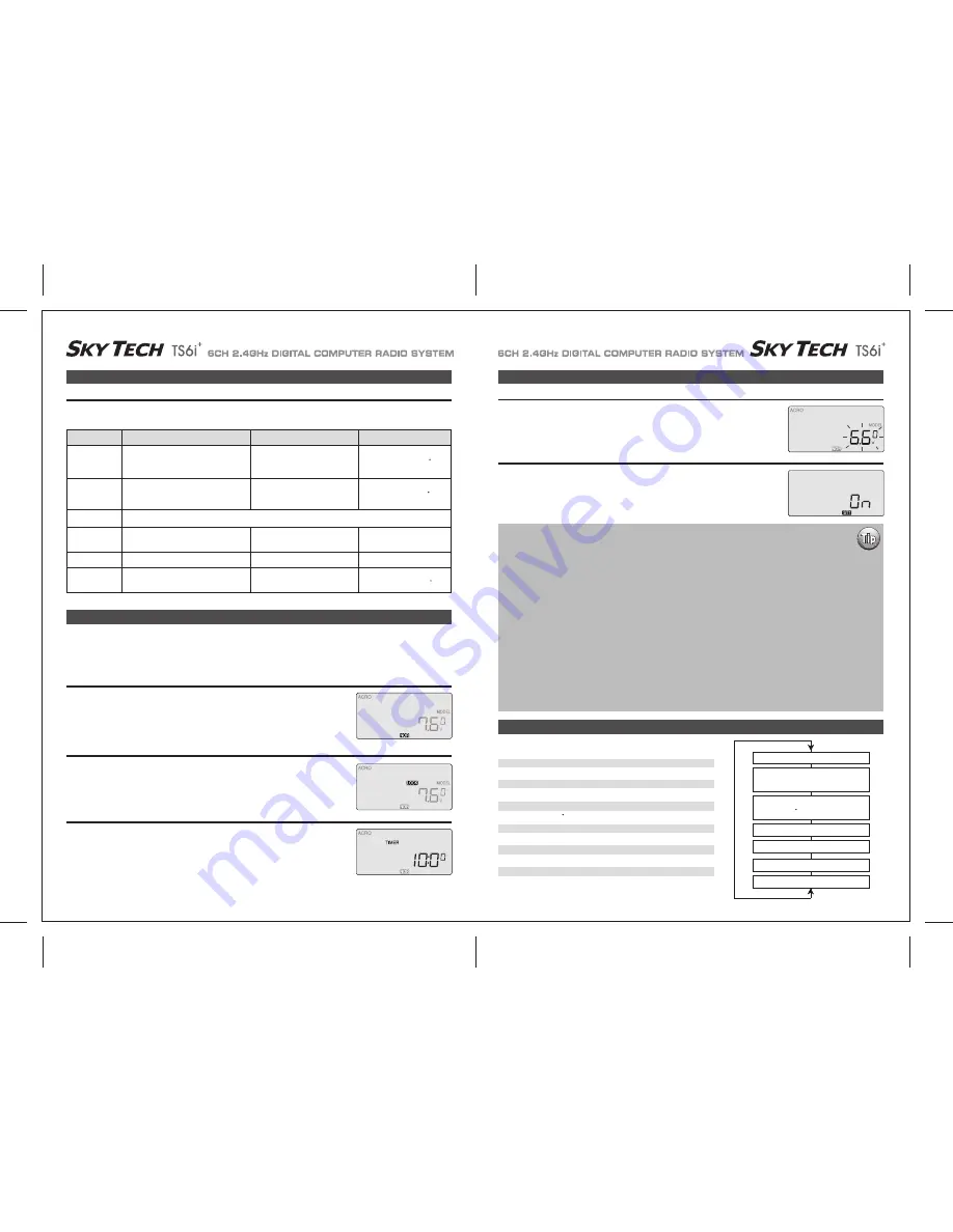
Receiver-Servo Connection List
Transmitter Displays and Messages
Transmitter Displays and Messages
Initial Setup Menu Programming for All Aircraft
Receiver-Servo Connection List
The table below shows where the aircraft's servos should plug into a six-channel receiver. Note that some functions shown will not operate
until they are activated in the transmitter. The standard function is listed first for each channel.
When you first turn on your transmitter, the first screen shown below appears on the LCD display. Before flying, or even starting the engine,
BE SURE that the model number appearing next to the voltage matches the model that you are about to fly! If you don't, reversed servos and
incorrect trims will lead to an immediate crash.
If you press timer or engine cut or lock keys, you go directly to those functions regardless of the display.
This screen appears whenever you turn on the transmitter without pushing any other buttons. The
model number currently enabled is the small number just to the right of the battery voltage and the
programming baseline for this model (ACRO, GLID or HELI) is shown in the upper left hand
corner. In the center bottom of the screen "NOR" appears in a small black box indicating that the
transmitter is in the "Normal" flight mode condition.
If you push either DATA button, you will enable the radio's timer mode.
The word "TIMER" appears on the screen as well as a number indicating the starting countdown
time (which you can set in the Initial Setup menu). If you push the right hand CURSOR button, the
timer will start counting down and the numbers will diminish in one-second increments. Push it
again and the countdown stops.
Pushing the left hand CURSOR button resets the timer.
When you push the Lock button to hold the throttle at an idle, the word "LOCK" appears in a black
box above the voltage value.
When you push the lock button again, this symbol disappears to indicate that you have disabled
the function.
Rx. Ch.
ACRO
GLID
HELI
Aileron
Aileron
Roll Cyclic
or Right Flaperon (FLPN ON)
or Right Aileron (ADIF on)
or Swash servo 1 (120 )
or Right Elevon
Elevator
Elevator
Pitch Cyclic
or Right V tail (VTAL on)
or Right V tail (VTAL on)
or Swash servo 2 (120 )
or Left Elevon (ELVN on)
Throttle (BEC In / Motor Signal Out)
Rudder
Rudder
Tail Rotor
or Left V tail (VTAL on)
or Left V tail (VTAL on)
Landing Gear
Left Aileron (ADIF on)
Gyro Gain
One
Two
Three
Four
Five
Six
Flap
Flap
Collective
or Left Aileron (FLPN on)
or Swash Servo 3 (120 )
Startup Screen
Lock Indicator Screen
Timer
When the battery's voltage drops to 6.6 volts, this number starts blinking on the screen and the
transmitter begins to steadily beep.
If your plane is up in the air when this happens, land immediately so you can recharge the battery.
Warning Display (Low voltage)
If you turn the transmitter on and it immediately starts to beep while displaying the word "ON" on
the screen, one of the flight condition modes other than Normal is switched on.
The symbol in the black box at the bottom of the screen indicates which switch (SW1 or SW3)
needs to be reset to Normal.
Warning Display (Flight Condition other than NOR)
If this is your first Airplane
If this is your first model Airplane, here are a few tips that will streamline your experience in programming it.
This will make more sense after you read through the manual.
Refer back to this section when you are ready to begin the setup:
1. Start with the correct model type, ACRO, in the Initial Setup Menu.
2. Access the main programming menu, then use the REV function, and make sure all the servos are moving in the
proper direction.
3. After centering the servo arms manually as close as you can, use the S.TRM or sub-trim function to center the
servos.
4. Set your servo end points with the EPA function.
5. Program -35% EXPO values for aileron, Ch. 1 and elevator, Ch. 2.
6. After your Plane is all ready to fly, put it on a shelf and go get an R/C flight simulator program for your PC.
Spend quality time crashing the virtual plane in the simulator. Using a sim will save you hundreds of dollars
spent on spare parts and countless hours of rebuilding time in the long run.
7. Ready to fly your new Plane? If you are lucky you will know someone that is an experienced model pilot and
would be willing to check over your plane and take it up for its first flight. This is HIGHLY RECOMMENDED, even if
you have to drive a hundred miles to get to this person! If you are on your own, start slow and conservatively.
Map of Basic Menu Functions
MODEL
Model select: choose on of ten model memories
14
ACRO
Acrobatic model mode
14
GLID
Glider model mode
14
HELI
Helicopter model mode
14
SWAH 90
Nomal Swash Plate (HELI only)
14
SWAH 120
120 Swash Plate (HELI only)
14
TMER
Timer setup
15
MODE 1
Transmitter mode 1
15
MODE 2
Transmitter mode 2
15
SFT N
Negative Transmit Shift
15
SFT P
Positive Transmit Shift
15
RST
Reset memory
15
Model Select 0~9 [MODEL]
Model Type
[ACRO] or [GLID] or [HELI]
Swash Plate type (HELI only)
[90] [120 ]
Timer setup [TIMER XX]
Mode 1 and Mode 2
Shift Dir. [SFT N] [SFT P]
Reset Memory [RST]


