


Page 34
Page 33
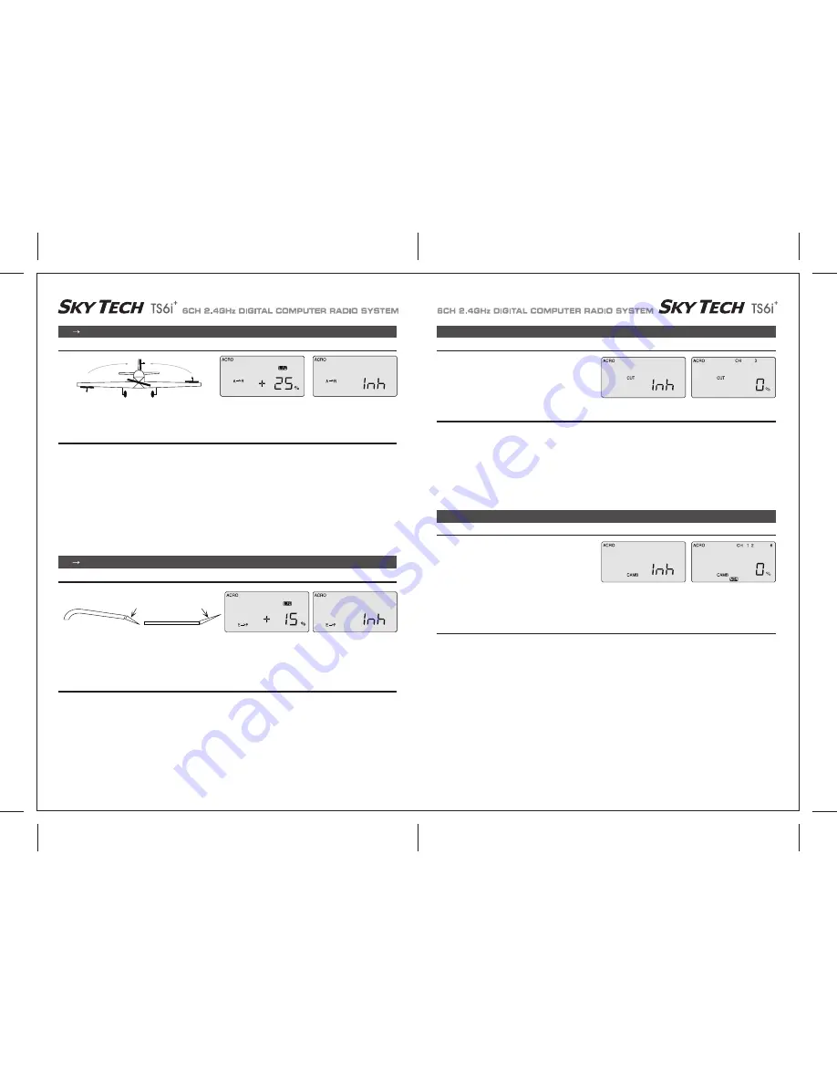
A R (Aileron-Rudder Mix)
A R (Aileron-Rudder Mix)
CUT (Engine Cut Function)
CAMB (Wing Camber)
This pre-programmed aileron-rudder mix allows you to slave a certain amount of rudder movement with the movement of the ailerons to gain
automatically coordinated turns. In addition to aileron differential, this mix reduces the yawing of the fuselage when the ailerons bank the wing.
This mix is especially useful for making the turns of slower-flying scale models appear more realistic.
A
→ R (Aileron-Rudder Mix)
This program allows you to set a certain amount of elevator-to-flap mixing so that the flaps (or flaperons if you've activated this mix) move
downward slightly when you pull back on the elevator stick. This is a favorite mix for pylon racing and 3-D aerobatics as a downward flap
movement combined with up-elevator movement enables the plane to snap-turn more quickly.
E
→ F (Elevator-Flap Mix)
1) In the A-R screen, activate the function by pressing both DATA buttons at once. The "Inh" symbol disappears and is replaced with a
percentage value (100% is the default).
2) Hold the right-hand joystick to the left, and use the - DATA button to reduce the value to a reasonable mix to begin with, say 25%.
3) You're not done yet, though-we have the same issue with the stick we encountered in the end point adjustment (EPA) screen.
If you move the aileron joystick to the right, the value goes back to the default 100% setting. Hold the stick to the right and reduce the value
to 25% here as well.
4) Now watch the rudder move as you move the joystick right and left-as the right wing's aileron moves up, the rudder should swing about
one-quarter of its travel to the right-and to the left with left-hand stick travel.
The optimum value of the mix can only be determined by flying the model: If the nose of the airplane yaws to the right when you bank left,
there is too little coupling-increase the rudder travel value. If it veers to the left (with the bank) there is too much
Setting up a Rudder-to-Aileron Mix
1) In the E-F screen, activate the function by pressing both DATA buttons simultaneously. The "Inh" symbol disappears and is replaced with
a percentage value (100% is the default).
2) Now hold the right-hand joystick all the way back (for full up elevator) and then, as you watch your model, change the value to gain the
amount of down-flap movement you want at full up-elevator. You probably won't need more than 15%, but only in-flight testing will tell
you for sure.
3) Finally, push the stick forward and reduce the value to 0 %-you generally don't want the flaps going up when you push the elevator stick
forward.
Setting Up an Elevator-to-Flap Mix
In this screen you can set the throttle's servo travel value (you
can also choose the direction in the program) so that you can
immediately cut off the motor when the engine is below half
throttle with a push of the "Eng Cut" button located on the
upper right-hand corner of the transmitter case.
CUT (Engine Cut Function)
This program allows you to initiate a mixing of the ailerons ith
flaps or Flaperon to camber the trailing edge downward or reflex
it upwards. Camber changes the airfoil to create more lift as you
slow the aircraft down for landing or to make a scale model fly
more slowly and realistically. You will also be able to set the
travel of the elevator on this menu screen to compensate for the
model's tendency to nose up when the flaps and ailerons droop
down together.
CAMB (
W
ing Camber)
1) To use the ailerons as flaperons to slightly droop down in unison to camber the wing we first need to get into the FLT C screen in order to
put the flaperons action on the three-position SW-3 "FLT Mode" switch on the upper right-hand top of the transmitter case. Use the
right-hand EDIT button to move down to the FLT C screen.
2) Start with the SW-3 switch in the middle position. Now move it toward the front of the case and you'll notice that the "Inh" symbol comes on
and the "NOR" symbol in the black box changes to "ST-2". Activate this switch position by pushing both DATA buttons simultaneously.
Now we are ready to feed in values for the ailerons and elevator (for pitch compensation) when you pull the switch toward you.
(You could, of course, choose to activate the mode with the switch pushed all the way back (ST 1) if that is more intuitive for you.)
3) Move back up one screen with the EDIT button to the CAMB screen.
4) With the SW-3 in the middle, "NOR" position, check to be sure that the values for channels 1, 2 and 6 all read 0%.
Now pull the switch toward you-"ST 2" appears instead of "NOR"-and use a DATA button to set the downward travel value for the
right-hand aileron to 25% (+ or - depending on your servo orientation.)
5) CURSOR over to channel 6 and set the left-hand aileron to deflect 25% down as well.
6) To set a bit of downward compensation in the elevator travel (we are assuming your airplane will likely nose upward when the camber is
activated), CURSOR over to channel 5 and set 15% of downward deflection.
As always, you will likely have to change all these values somewhat when you get the model up into the air.
Setting Up
W
ing Camber and Elevator Compensation
1) In the "CUT" screen, un-inhibit the program by pushing both DATA buttons-a percentage value comes up on the screen (default is 0%).
2) Use either DATA button to change the value to a setting(you can go positive or negative up to 75%) that moves your throttle servo to the
point where its pushrod fully closes the motor's carburetor. (You activate the servo cut movement by pushing the "ENG CUT" button on
the upper right portion of the transmitter case.)
3) Watch the servo movement on your model carefully:
You don't want to overdo the travel value or you'll stall the servo (you'll probably hear it buzzing if its stalled-which creates a drain on the
on-board battery and a potential over-heating problem for the servo).
Setting The Engine Cut Function
UP elevator
DOWN flap or flaperon
E F (Elevator-Flap Mix)


