


Page 36
Page 35
A R (Aileron-Rudder Mix)
FLT. C (Flight Conditions)
FLT. C (Flight Conditions)
This is a sophisticated function of the Sky Tech TS6i
+
's
programming that allows you to activate up to four different flight condition modes with switches SW-1 and SW-3.
In these modes you can select four different amounts of dual-rate, exponential and flaperon and elevator settings for each switch position. We
already demonstrated this function previously when we set up one additional flight mode with camber settings.
Having the ability to set up four flight modes with different dual-rate and exponential functions offers some useful nuances of flight control
when you are flying in changing weather conditions or performing advanced aerobatics.
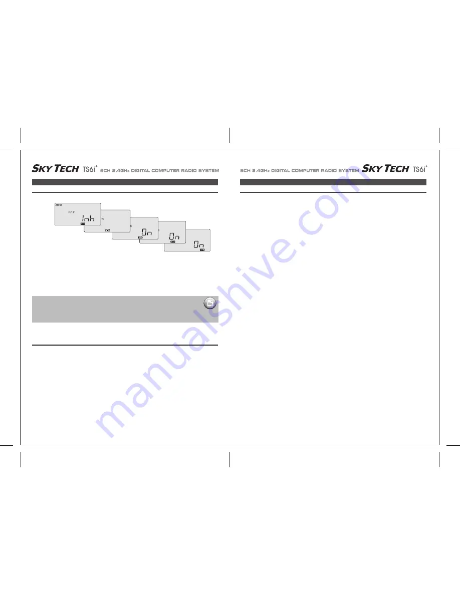
FLT. C (Flight Conditions)
1. Move both mode switches to their normal positions: SW-1 toward the back "0" and SW-3 to the middle).
2. To activate a flight mode on switch SW-1 move the switch position toward you to "1" and hit both DATA buttons simultaneously.
The "Inh" symbol will change to "On" and ST3 will be blinking. Now move the switch back to the "0" position.
3. To activate two more flight modes, move switch SW-3 from its center position (NOR) toward the back of the transmitter.
Activate the mode ST1 by hitting both DATA buttons simultaneously. The "Inh" symbol will change to "On" and ST1 will be flashing.
4. Move switch SW-3 to the front of the transmitter. Activate the mode ST2 by hitting both DATA buttons simultaneously.
The "Inh" symbol will change to "On" and ST2 will be flashing.
5. The middle position, normal (NOR), is by default the fourth flight mode.
To activate a certain flight mode condition while in flight, simply move the appropriate switch. Note that SW-1 over-rides SW-3 in any of its
three positions
Setting up Flight Condition Modes
Setting Up Flight Condition Modes with Different Dual Rate and Exponential Values
Let's set up two dual-rate and exponential settings in addition to those established with the switch SW-3 in the center, normal (NOR) position.
We'll assume that you have already activated modes ST1 and ST2 on this switch as instructed above:
1. Enter the Main Function menu by pressing both EDIT buttons with the transmitter on.
2. Scroll to the dual rate (D/R) screen with the Right EDIT button:
CH 1 should be flashing and "NOR" should appear at the bottom of the screen under the default value of 100%.
(If it isn't, you can return to the default value immediately by pressing the Clear button). Next to the 100%, a "0" indicates that switch SW-2
is in the 0 position-if it isn't, put it there.
3. Using one of the DATA buttons, enter a rate value for the ailerons in CH 1-then move switch SW-2 to the "1" position and enter another
value. This will be the dual-rate range for the ailerons in the normal (NOR) flight mode.
4. To establish a second set of dual rates for the ailerons in flight condition mode ST1, move the switch SW-3 to the back of the case: ST1
appears. Now set a dual rate when the switch SW-2 in the "0" position and then in the "1" position.
5. To establish a third set of dual rates for the ailerons in flight condition mode ST2, move the switch SW-3 to the front of the case: ST2
appears. Now set a dual rate when the switch SW-2 in the "0" position and then in the "1" position.
6. If you wish to set dual-rate ranges for the elevator and the rudder follow the last three steps above-entering in the values in elevator CH 2
and then in rudder CH 4.
7. To establish the two additional flight mode exponential settings, scroll to the EXP screen and follow essentially the same process outlined
above for setting the dual-rate ranges.
(Note that both the dual-rate and exponential settings are toggled on the same switch: SW-2).
If you turn on your radio with one (or more) of the switches turned on to an activated flight condition,
the radio will start beeping at you and the screen will inform you which switch is on. If this happens
don't panic: simply move the switch(s) until the beeping stops and the "NOR" symbol appears.
IMPORTANT NOTE :


