ACE RC sky tech TS6i+ Instruction Manual Download Page 15

Page 28

Page 27  

D/R  (Dual Rate)

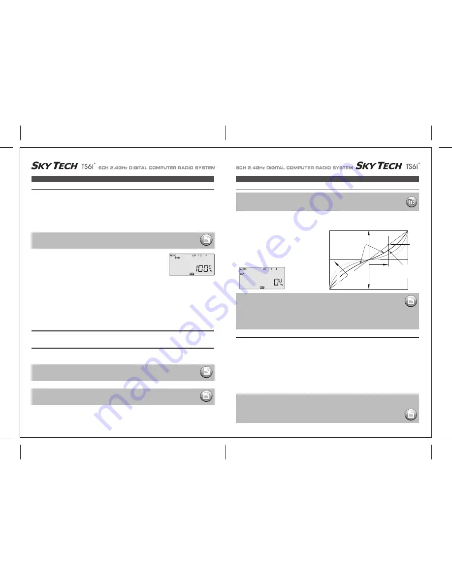
EXP (Exponential Rate)

If this is your first computer radio, you may have never been introduced to dual rates before.
Dual rates-which allow you to reduce the travel of the aileron, elevator and rudder servos with the flick of one switch 
(SW-2 on the Sky Tech TS6i

+

) are often used to tone down the control throws when flying at higher speeds-without this ability, its possible to 

be really gentle with the controls and yet still over-control a fast-moving model.
When you flick on a lower throw rate for the servos, you instantly reduce the radical response of the model to your control inputs.
This ability is a boon for beginning pilots and very useful even for experts.
The amount of travel reduction (or increase for wild aerobatics!) may be set anywhere between 0 and 125%. Get to the D/R menu by pressing 
one of the Up Down EDIT buttons repeatedly until the D/R dual rate screen appears, as shown.

This function-which may also be new to first-time computerized radio users-allows you to choose the exponential value for the ailerons, 
elevator and rudder. 
Applying exponential enables you to "soften" the stick throws to take out the "twitchiness" of your model's response to your control inputs. The 
greater the negative value you specify, the less effect the sticks 
have around their center points-and the less effect your twitchy 
fingers have on your model's performance. (Conversely, positive 
exponential makes the servos very sensitive around neutral and soft 
at the extreme stick throws-an effect best left to the experts!) Like 
the dual-rate programming, you can apply or remove this function 
with switch SW-2.

Press the Right Cursor key again to get "4" blinking. Now set the rudder dual rates in the same way you set the ailerons and elevator in the 
previous steps.

1. Press the Right CURSOR button to get the channel "1" blinking (if it isn't already by default): The 

default value showing on the screen should be 100% - but notice the extra little zero next to the 
100. This indicates that the rate is this value (100%) when the switch SW-2 on the upper right 
hand corner of the transmitter case is set in the 0 position (check out the label by this switch). Flick 
the switch toward you-the number 1 will come on next to the 100.
For now, leave the rate at 100% in the 0 switch position, but let's change the rate for CH 1 when 
you move the switch to 1. 

2. With the switch SW-2 forward and "1" showing next to the default 100 value, reduce the value to 

75% by pushing down on the “

” DATA button. Now whenever you move switch SW-2 to the 1 

position, the travel of the ailerons (note that the second aileron is automatically affected) will be 
75% of the "normal" 100% value.
When flying the plane you will quickly see if 75% is enough of a reduction-if not, you can always 
come back and change it in this screen.
(This is true, or course, for all the parameters we are going to establish in this menu set).

D/R  (Dual Rate)

Press the Right Cursor key one time to get Channel "2" blinking.  With the switch in the "1" position, set the elevator dual rate to 75%. 

Setting up dual rates on the elevator 

Setting up rudder dual rate 

EXP (Exponential)

1) Push the CURSOR buttons repeatedly until the channel "1" is blinking. 
2) The default exponential value is 0%. To create some softness around the neutral position of the stick, we want to apply some negative     

exponential. With switch SW-2 set in the "1" position, push the - DATA button until the screen indicates -25%--a typical exponential value    
for ailerons.
You can, of course, increase or decrease this amount as you get a feeling for how the plane flies. 

3) Move over to CH 2 with the CURSOR and set -25% on the elevator; move to CH 4 and set -25%--again these are arbitrary starting points     

subject to your personal preference.
Notice that when you push the SW-2 switch back to its "0" position all the exponential values return to their default zero settings.

4) If you want, you can have some "expo" on any or all three of these channels by setting a value with the switch in the "0" position.

To quickly get back to the default 0%, press the Clear button.

5) Return to the regular operating mode by pressing the two EDIT Up Down buttons simultaneously.

Setting Up Exponential

if you set the dual rate amount to zero, you will get no response from that channel, which may cause a 
crash when you switch to this rate setting.. 

NOTE:

The values you set for exponential are highly dependent on both the model and pilot's preference. 
We recommend a start value of about -25 to -35%, and, after test flying, slowly increasing the number until 
things feel "right". 
Obviously this depends on the pilot and model so go ahead and fly it with Expo only on one side of the switch, 
turn it on and off during flight, and change the values to suit yourself. 
Or don't use it at all if you don't like it - it's not for everyone.

NOTE:

You should understand that you won't see changes in your model's servo response unless you move the sticks. 
To get a feel for how exponential works, hold partial stick and watch the control surfaces as you switch the 
Expo on and off (one side of the switch should be set to zero expo in this case).

Once each flight condition is activated, you can set EXP for each flight condition respectively.

NOTE:

If you quickly want to get back to the default 100%, press the Clear button

NOTE:

Once each flight condition is activated, you can set D/R for each flight condition respectively.

NOTE:

Exponential ("Expo") is great for beginners and highly recommended. 
Try it out. Your flying will be smoother and more controllable, reducing the stress most beginners feel 
when learning to fly.

Servo

Response

Stick Motion

Negative Exponential 

gives smaller response for 

same stick motion

around neutral

Normal 

linear

response

Increasing negative 

exponential

(shallower around 

neutral)

0% 

(Linear)

-25%

-50%

-75%

Much less response 

around neutral (Compare

with Normal line)

Summary of Contents for sky tech TS6i+

Page 1: ...TEM 6CH 2 4GHz DIGITAL COMPUTER RADIO SYSTEM 6CH 2 4GHz DIGITAL COMPUTER RADIO SYSTEM Function Assignable Switches Easy to Read LCD Screen Built in ACE RC AFHSS 2 4GHz System 0678 INSTRUCTION MANUAL V...

Page 2: ...ion of this radio is that your models require six or less control channels If Sky Tech TS6i is your first programmable radio control transmitter you re probably feeling a bit overwhelmed by all the bu...

Page 3: ...r the servo rails the rubber grommets will not be able to attenuate vibration which can lead to mechanical wear and possible servo failure The Sky Tech TS6i can be used with most of the ACE RC s exist...

Page 4: ...he control sticks and trims alone then moving the control sticks 4 The instructor s transmitter has normal control over the model unless the trainer button is pressed passing control to the student s...

Page 5: ...amage or injury to anyone nearby Finally don t fly in the rain Water or moisture may enter the transmitter through the antenna or stick openings and cause erratic operation or loss of control Before y...

Page 6: ...timer CURSOR buttons As the and symbols imply these buttons allow you to change a numerical value most often a value of servo travel up or down within a menu item When not in the programming mode eith...

Page 7: ...AFHSS 2 4GHz System The TRS603DD is loaded with a variety of functions that are sure to deliver a satisfying R C experience The TRS603DD receiver is offered as a standard receiver for the Sky Tech TS...

Page 8: ...ed to use a large capacity BEC when a number of high torque servos are used and power requirements exceed that which the ESC provides Turning Off Turn off the receiver then turn off the transmitter Tu...

Page 9: ...moving properly do not fly the aircraft until the problem is solved Range Check Do a complete range check as described on page 21 before each flying session to confirm the radio system is working prop...

Page 10: ...signal radios 2 4GHz systems use a fixed shorter stubby transmitter antenna so the traditional method of range checking your system by lowering the transmitter antenna will not work We instead use a...

Page 11: ...lap Collective or Left Aileron FLPN on or Swash Servo 3 120 Startup Screen Lock Indicator Screen Timer When the battery s voltage drops to 6 6 volts this number starts blinking on the screen and the t...

Page 12: ...hand EDIT button to move to the next menu screen 2 Select the Model type programming baseline If you selected HELI as your model type this screen will appear allowing you to select between NORMAL 90...

Page 13: ...old which mode is currently active Now push down both EDIT buttons at the same time The following menu items will appear as you scroll down the list by pushing down the right hand EDIT button POWER Tr...

Page 14: ...setting procedure for left rudder Rudder End Points In the same manner as described above set EPA values for channel 5 landing gear or flaps if your model has these functions Flap or Landing Gear End...

Page 15: ...e or course for all the parameters we are going to establish in this menu set D R Dual Rate Press the Right Cursor key one time to get Channel 2 blinking With the switch in the 1 position set the elev...

Page 16: ...move over to CH 2 and push both DATA buttons simultaneously You ll notice that the symbol NOR ahead of CH has changed to REV and that the servo is now operating as it should on your model If any othe...

Page 17: ...s are stalling at their maximum throw turn down the value in the EPA screen or move the pushrod further up on the aileron horn to physically reduce the throw This is another built in mixing program av...

Page 18: ...Eng Cut button located on the upper right hand corner of the transmitter case CUT Engine Cut Function This program allows you to initiate a mixing of the ailerons ith flaps or Flaperon to camber the...

Page 19: ...exponential settings in addition to those established with the switch SW 3 in the center normal NOR position We ll assume that you have already activated modes ST1 and ST2 on this switch as instructed...

Page 20: ...Combined Flaps Ailerons 34 FLT C Flight Condition NOR ST1 ST2 ST3 If this is your first Sailplane If this is your first model Sailplane here are a few tips that will streamline your experience in prog...

Page 21: ...ction usually about twice as much UP movement as DOWN is an especially important quality for sailplanes as differential reduces the parasitic drag due to a yawing fuselage and unnecessary aileron trav...

Page 22: ...the elevator will move down very slightly relative to its normal angle of incidence This allows the glider to quickly fly between thermals and through areas of sink Thermal With the SW 3 switch pushed...

Page 23: ...plate type 120 is also referred to as SN 3 Heli SwashPlate POWER Trainer Engine Cut Switch SW 3 SW 1 Rudder Throttle Stick Aileron Elevator Stick Plastic Side Panel SW 2 Antenna Trim Switch Power Swit...

Page 24: ...ntrol the RPM of the motor The Speed Control may have settings that need to be programmed so check the Speed Controller manual 2 In smaller electric heli s a large motor battery provides the power for...

Page 25: ...dy for making the control less sensitive there P CV Pitch Curve 1 Press one of the Up Down EDIT buttons until the P CV window appears The default is for a linear curve a straight line from 0 to 100 pa...

Page 26: ...de SW 3 switch all the way back NOR will be flashing on and off Set the percentage to yield the desired gyro gain this is usually a high gain setting If for some reason you want a 0 setting press the...

Page 27: ...up the swash screen by repeatedly pressing one of the Up Down EDIT buttons until the SWAH window appears The function is automatically active when you select 120 mixing in the model setup menu 5 If al...

Page 28: ...L U L U L U R D R D R D R D R D R D MAS SLV ON OFF STICK SERVO STICK SERVO ON INH STICK SERVO ON INH NOR ST1 ST2 ST3 ON ON OFF ON OFF ON OFF 1 2 AILE CH1 AILE CH5 ON INH ON INH ON INH NOR ST1 ST2 ST3...

Reviews: