


MC97F6108A User’s manual
11. PPG (Programmable Pulse Generator)
99
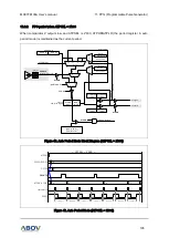
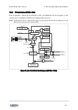
11.4
Capture mode
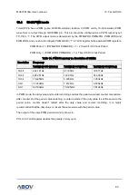
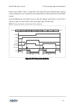
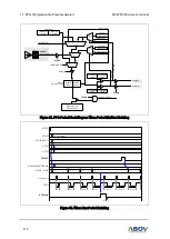
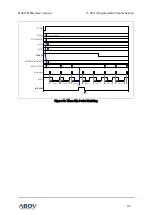
PPG capture mode is set by CAPE
as ‘1’ in
PPGCR register. The capture result is loaded into
PPGCH/PPGCL. The counter (PPGH/PPGL) does not stop when counter is captured. Capture sources
are CMP3IF, CMP1IF and CMP4IF. And then function is chosen. The capture source is selected by
setting PPGIN[2:0] in the PPGCR1 register.
PPGCH and PPGH are in same address. In the capture mode, reading operation is read the PPGCH,
not PPGH because path is opened to the PPGCH. The PPGL, PPGCL has the same function.
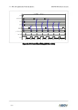
DUTY
CMP3IF
(CIFLAG.3)
PPGO
PERIOD
DUTY
PERIOD
0 1 2 3 4 5 6 7 A B C D E
0 1 2 3 4 5 6 7 A B C D E
0
5
6
PPGCH, PPGCL
{PPGPH, PPGPL} = 0x0E, {PPGDH, PPGDL} = 0x03, PPGIN = 010b (CMP3IF)
start pulse
PPGH,PPGL
-
-
PPGIN[2]
PPGIN[1]
PPGIN[0]
-
PPG_PE
-
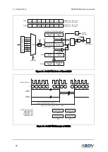
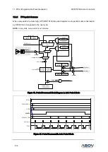
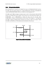
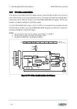
PPGCR1
ADDRESS :
E3
H
PPGEN
-
CAPE
PPGCK2
PPGCK1
PPGCK0
PPGCN
PPGST
PPGCR
ADDRESS :
E2
H
CAPE
Figure 36. Capture Mode