


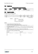


17. Power down operation
MC97F6108A User’s manual
186
17.3
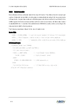
STOP mode
Power control register is set to ‘03H’ to enter into STOP mode. In STOP mode, the selected oscillator,
system clock and peripheral clock is stopped, but basic interval timer and watchdog timer can be
continued to operate with WDTRC OSC.
With the clock frozen, all functions are stopped, but the on-chip RAM and control registers are held.
Sources to exit from STOP mode is hardware reset and interrupts. The hardware reset re-defines all
control registers. When awaking from STOP mode, enough oscillation stabilization time is required to
normal operation. Figure 84 shows the timing diagram.
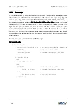
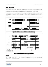
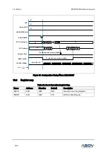
As shown in Figure 84, when released from STOP mode, the basic interval timer is activated on wake-
up. Therefore, before STOP instruction, a user must set relevant prescaler divide ratio to have long
enough time. This guarantees that an oscillator has started and stabilized.
Figure 84. STOP Mode Release Timing by External Interrupt
OSC
CPU Clock
External
Interrupt
Normal Operation
BIT Counter
STOP Operation
Normal Operation
Release
STOP Instruction
Execute
Clear & Start
By Software setting
Before executed STOP instruction, BIT must be set properly by
software to get stabilization time. Time has to be longer than 20ms..
n
n+1
n+2
n+3
FF
0
1
1
2
FE
0
T
OSC
= 1/f
OSC
BPD[2:0] in BCCR = 111
B
TST > 20ms by Software