


MC97F6108A User’s manual
4. Memory organization
29
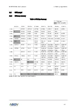
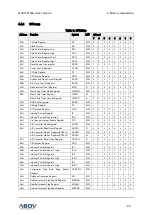
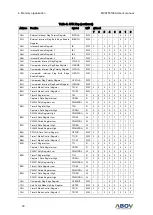
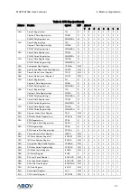
4.4.2
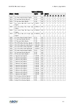
SFR map
Table 5. SFR Map
Address Function
Symbol
R/W
@Reset
7
6
5
4
3
2
1
0
80H
P0 Data Register
P0
R/W
0
0
0
0
0
0
0
0
81H
Stack Pointer
SP
R/W
0
0
0
0
0
1
1
1
82H
Data Pointer Register Low
DPL
R/W
0
0
0
0
0
0
0
0
83H
Data Pointer Register High
DPH
R/W
0
0
0
0
0
0
0
0
84H
Data Pointer Register Low 1
DPL1
R/W
0
0
0
0
0
0
0
0
85H
Data Pointer Register High 1
DPH1
R/W
0
0
0
0
0
0
0
0
86H
Reset Source Flag register
RSFR
R/W
1
0
0
0
1
-
-
-
87H
Power Control Register
PCON
R/W
0
–
–
–
0
0
0
0
88H
P1 Data Register
P1
R/W
0
0
0
0
0
0
0
0
89H
P0 Direction Register
P0IO
R/W
0
0
0
0
0
0
0
0
8AH
System and Clock Control Register
SCCR
R/W
0
–
0
–
–
–
0
0
8BH
BIT Clock Control Register
BCCR
R/W
0
0
0
0
0
1
0
1
8CH
Basic Interval Timer Register
BITR
R
0
0
0
0
0
0
0
0
8DH
Watch Dog Timer Mode Register
WDTMR
R/W
0
0
0
0
–
–
–
0
8EH
Watch Dog Timer Register
WDTR
W
1
1
1
1
1
1
1
1
Watch Dog Timer Counter Register
WDTCR
R
0
0
0
0
0
0
0
0
8FH
BOD Control register
BODR
R/W
–
0
–
–
0
0
0
1
90H
P2 Data Register
P2
R/W
–
–
–
–
–
–
0
0
91H
P1 Direction Register
P1IO
R/W
0
0
0
0
0
0
0
0
92H
Interrupt Priority Register
IP
R/W
–
–
0
0
0
0
0
0
93H
Interrupt Priority Register High
IPH
R/W
–
–
0
0
0
0
0
0
94H
Pin Change Interrupt Enable Register
PCI
R/W
0
0
0
0
0
0
0
0
95H
A/D Converter Mode Register
ADCM
R/W
1
0
0
0
1
1
1
1
96H
A/D Converter Result Low Register
ADCRL
R
x
x
x
x
x
x
x
x
A/D Converter Mode 1 Register(STBY=1)
ADCM1
R/W
–
0
0
0
–
0
0
1
A/D Converter Mode 1 Register(STBY=0)
ADCM1
W
–
0
0
0
–
0
0
1
97H
A/D Converter Result High Register
ADCRH
R
x
x
x
x
x
x
x
x
99H
P2 Direction Register
P2IO
R/W
–
–
–
–
–
–
0
0
9AH
Interrupt Priority Register 1
IP1
R/W
–
–
0
0
0
0
0
0
9BH
Interrupt Priority Register 1 High
IP1H
R/W
–
–
0
0
0
0
0
0
9CH
Interrupt Priority Register 2
IP2
R/W
–
–
0
0
0
0
0
0
9DH
Interrupt Priority Register 2 High
IP2H
R/W
–
–
0
0
0
0
0
0
9EH
Interrupt Priority Register 3
IP3
R/W
–
–
0
0
0
0
0
0
9FH
Interrupt Priority Register 3 High
IP3H
R/W
–
–
0
0
0
0
0
0
A0H
Comparator Flag Both Edge Enable
Register
CFBOTH
R/W
–
–
–
0
0
0
0
0
A2H
Extended Operation Register
EO
R/W
–
–
–
0
–
–
–
0
A3H
External Interrupt Flag Enable Register
EIENAB
R/W
–
–
–
–
–
0
0
0
A4H
External Interrupt Flag Register
EIFLAG
R/W
–
–
–
–
0
0
0
0
A5H
External Interrupt Flag Edge Register
EIEDGE
R/W
–
–
–
–
–
0
0
0