


MC97F6108A User’s manual
12. Analog comparator and OP-AMP
125
12
Analog comparator and OP-AMP
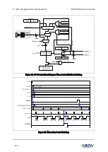
MC97F6108A has five analog comparators and two operational amplifiers whose inputs are external
analog inputs and whose outputs are sources of internal peripheral circuits.
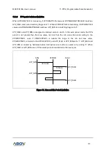
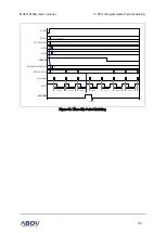
Each comparator has output noise canceler, de-bounce and interrupt circuits. De-bounce length for
each comparator is selectable by setting CxDBSEL[1:0]. The interrupt vector address of comparator
and control registers are described in interrupt controller section. In addition to the interrupt flags, each
comparator has comparator flags. Interrupt flags work only for interrupt and they are cleared by
hardware and software. But comparator flags are connected to PPG block and cleared only by writing
'0', some of them are cleared by PPG operation.
De-bounce output and flags of Comparator are connected to PPG, interrupt control block and timers
and comparator output port CMPXO(P01). By setting CMPOSL[2:0] register, one comparator is
selected to the port.
Internal reference voltage level of Comparator is selectable by software and CMPEN enables all
comparators.
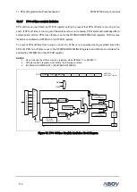
AMP1 output enters into the input of AMP2 and comparator 3. AMP2 output is connected to AMP2O
port through the voltage divider circuit. If voltage divider option is selected by setting AOSEL and
AORA_EN=1, AMP2 output is divided. If AORA_EN=0 and AOSEL=111111b, the voltage divider is
disabled. AMP2 output is directly connected to ADC block when AMP2O_EN = 1 and ADC channel 7
is selected. OPAEN enables OP-AMP operation.
OINPen, C0INNen, C0INPen, C1INPen and C2INPen enable each port to receive external analog
source and AMP1O_EN and AMP2O_EN enable AMP1 and AMP2 output to each port. In order to
prevent form the analog input entering to digital circuit, PSR register need to be set.