


7.5.2.1
Verifying the settings
Verification of START value and time delay to operate
M16290-14 v4.1.1
1.
Check that the IED settings are appropriate, for example the start value and the time
delay.
2.
Supply the IED with three-phase voltages at their rated values and initial frequency.
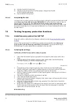
The initial frequency is calculated using Equation
.
0.02
/ 0.04
0.04
r
StartFrequency
floor f
StartFrequency
IECEQUATION16061 V1 EN-US
(Equation 21)
[2]
3.
Slowly increase the voltage frequency by steps of 40 mHz until the START signal appears;
during each step apply the voltage signal for a time that is either at least 10% longer than
(
100 ms) or a suitable time to monitor the function.
4.
Note the frequency value at which the START signal appears and compare it with the set
value
StartFrequency.
5.
Decrease the frequency until its rated value is reached.
6.
Check that the START signal resets.
7.
Supply the IED with three-phase voltages at their rated values and frequency 20 mHz
under the set value
StartFrequency.
8.
Increase the frequency with a 40 mHz step, applying it for a time that is at least 10%
longer than (
100 ms).
9.
Measure the time delay of the
TRIP signal, and compare it with the set value tDelay. Note
that the measured time consists of the set value of the time delay plus the minimum
operate time of the function (80 - 90 ms).
Extended testing
M16290-28 v4.1.1
1.
Check that the IED settings are appropriate, for example the start value and the time
delay.
2.
Supply the IED with three-phase voltages at their rated values and frequency 20 mHz over
the set value
StartFrequency, applying it for a time that is at least 10% longer than
(
100 ms).
3.
Verify that the TRIP signal is active.
4.
Decrease the frequency with a 40 mHz step, applying it until the TRIP signal resets.
5.
Measure the reset time of the
TRIP signal, and compare it with the technical data of the
function.
Verification of the low voltage magnitude blocking
M16290-34 v4.1.1
1.
Check that the IED settings are appropriate, especially the
StartFrequency and the tDelay
in SAPTOF, and the
GlobalBaseSel and the MinValFreqMeas in the SMAI preprocessing
function.
2.
Supply the IED with three-phase voltages at rated values.
3.
Slowly decrease the magnitude of the applied voltage until the BLKDMAGN signal
appears.
4.
Note the voltage magnitude value and compare it with the value
MinValFreqMeas x
UBase / 100.
Where:
•
MinValFreqMeas is a set value of the SMAI.
•
UBase is the value in the GBASVAL group identified by the setting
GlobalBaseSel.
5.
Slowly increase the frequency of the applied voltage, to a value above
StartFrequency as
Verification of START value and time delay to operate
.
6.
Check that the START signal does not appear.
[2] floor[
x] is the largest integer less than or equal to x
Section 7
1MRK 505 293-UEN B
Testing functionality
72
Breaker protection REQ650
Commissioning manual
© Copyright 2013 ABB. All rights reserved
Summary of Contents for REQ650 1.3 IEC
Page 1: ...Relion 650 SERIES Breaker protection REQ650 Version 1 3 IEC Commissioning manual ...
Page 2: ......
Page 12: ...6 ...
Page 20: ...14 ...
Page 28: ...22 ...
Page 40: ...34 ...
Page 42: ...36 ...
Page 116: ...110 ...
Page 123: ...117 ...


