


V
1
2
A
GUID-31DF5495-91F1-4A4B-8FD5-50625038961E V1 EN-US
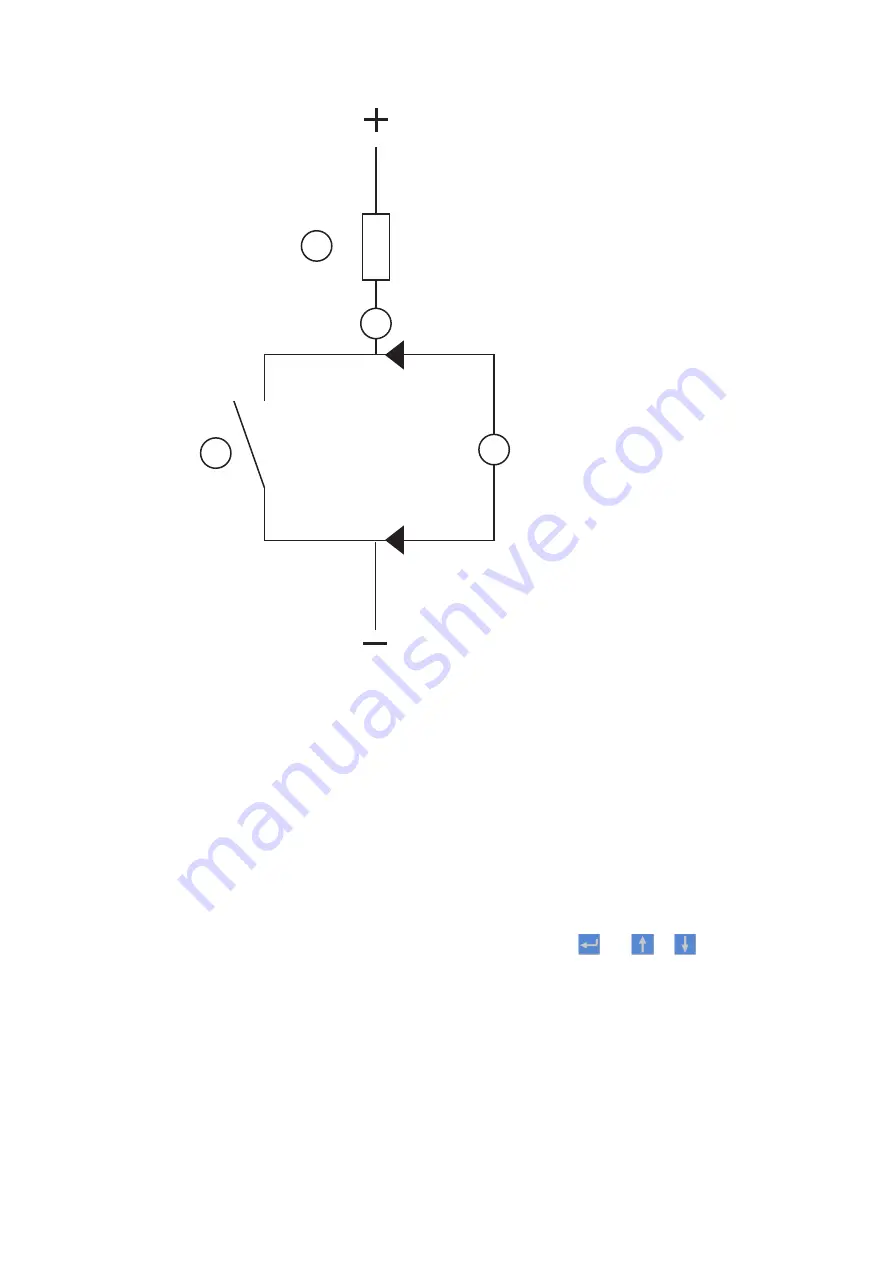
Figure 20: Testing a trip contact
1 Trip contact under test
2 Current limiting resistor
•
To check the status of the output circuits driving the output relay via the LHMI, select
Main menu/Tests/I/O modules and then navigate to the board with the actual binary
output to be checked.
•
Test and change the relay state manually.
1.
To set the IED to test mode, select Main menu/Tests/IED test mode/TESTMODE:1
and set the parameter to
On.
2.
To operate or force the output relay to operate, select and then navigate to the
board with the actual binary output relay to be operated/forced.
3.
Select the BOn_PO to be operated/forced and use
and
or
to operate the
actual output relay.
In PCM600, only the result of these operations can be checked by right-clicking the
product and selecting Signal Monitoring tool and then navigating to the actual I/O-
board and the binary input in question. The activated output signal is indicated with
a yellow-lit diode. Each BOn_PO is represented by two signals. The first signal in
LHMI is the actual value 1 or 0 of the output, and in PCM600 a lit or dimmed diode.
The second signal is the status Normal or Forced. Forced status is only achieved
when the BO is set to
Forced or operated on the LHMI.
Section 9
1MRK 505 293-UEN B
Troubleshooting
108
Breaker protection REQ650
Commissioning manual
© Copyright 2013 ABB. All rights reserved
Summary of Contents for REQ650 1.3 IEC
Page 1: ...Relion 650 SERIES Breaker protection REQ650 Version 1 3 IEC Commissioning manual ...
Page 2: ......
Page 12: ...6 ...
Page 20: ...14 ...
Page 28: ...22 ...
Page 40: ...34 ...
Page 42: ...36 ...
Page 116: ...110 ...
Page 123: ...117 ...


