


•
In LHMI, select Main menu/Tests/I/O modules. Then navigate to the board with the
actual binary input to be checked.
•
With PCM600, right-click the product and select Signal Monitoring. Then navigate to
the actual I/O board and to the binary input in question. The activated input signal is
indicated with a yellow-lit diode.
•
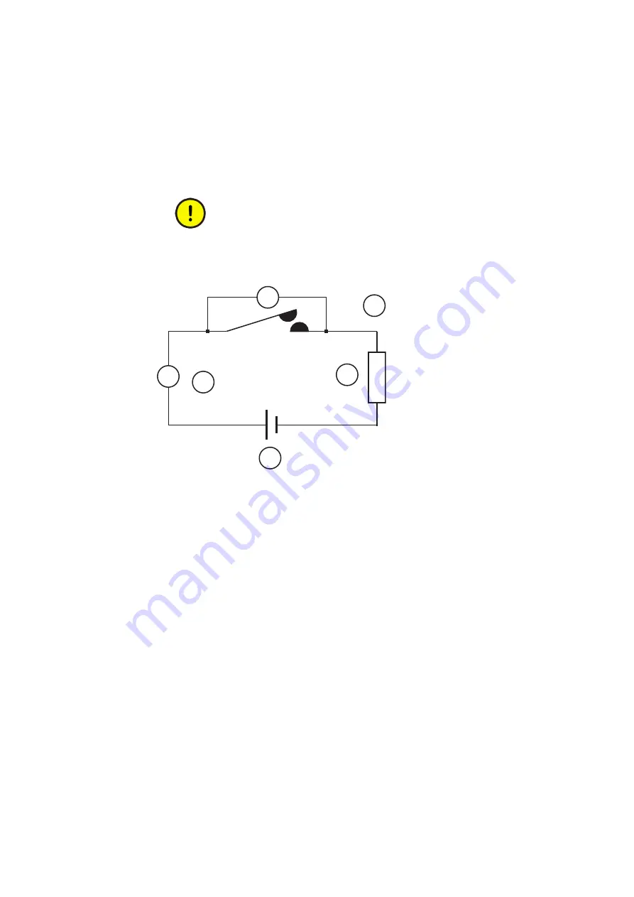
Measure output contacts using the voltage drop method of applying at least the minimum
contact load given for the output relays in the technical data, for example 100 mA at 24 V
AC/DC.
Output relays, especially power output relays, are designed for breaking
high currents. Due to this, layers of high resistance may appear on the
surface of the contacts. Do not determine proper functionality of
connectivity or contact resistance by measuring with a regular hand-held
ohm meter.
A
1
2
3
4
V
GUID-BBAEAF55-8D01-4711-A71D-BBC76B60BA3D V1 EN-US
Figure 19: Testing output contacts using the voltage drop method
1 Contact current
2 Contact voltage drop
3 Load
4 Supply voltage
1MRK 505 293-UEN B
Section 9
Troubleshooting
Breaker protection REQ650
107
Commissioning manual
© Copyright 2013 ABB. All rights reserved
Summary of Contents for REQ650 1.3 IEC
Page 1: ...Relion 650 SERIES Breaker protection REQ650 Version 1 3 IEC Commissioning manual ...
Page 2: ......
Page 12: ...6 ...
Page 20: ...14 ...
Page 28: ...22 ...
Page 40: ...34 ...
Page 42: ...36 ...
Page 116: ...110 ...
Page 123: ...117 ...


