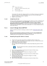


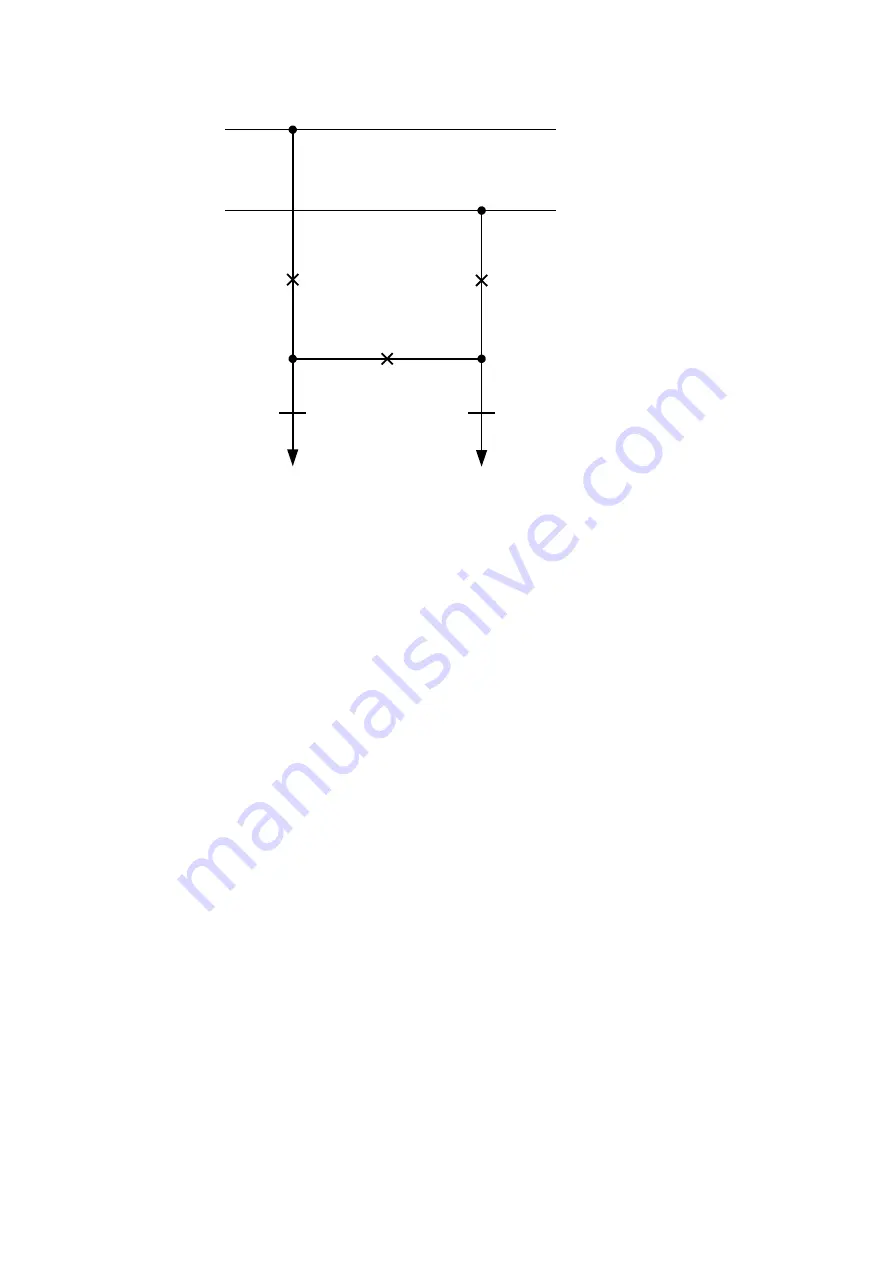
Bus 1
Bus 2
CB1QA1
(SESRSYN 1)
CB3QA1
(SESRSYN 3)
CB2QA1
(SESRSYN 2)
Line 1
Line 2
LN1QB9
LN2QB9
IEC11000274-2-en.vsd
IEC11000274 V2 EN-US
Figure 15: Objects used in the voltage selection logic
Testing the voltage difference
M2377-194 v6
Set the voltage difference to 0.15 p.u. on the local HMI, and the test should check that
operation is achieved when the voltage difference
UDiffSC is lower than 0.15 p.u.
The settings used in the test shall be final settings. The test shall be adapted to site setting
values instead of values in the example below.
Test with no voltage difference between the inputs.
Test with a voltage difference higher than the set
UDiffSC.
1.
Apply voltages U-Line (for example) = 80%
GblBaseSelLine and U-Bus = 80%
GblBaseSelBus
2.
Check that the AUTOSYOK and MANSYOK outputs are activated.
3.
The test can be repeated with different voltage values to verify that the function
operates within the set
UDiffSC. Check with both U-Line and U-Bus respectively lower
than the other.
4.
Increase the U-Bus to 110%
GblBaseSelBus, and the U-Line = 90% GblBaseSelLine and
also the opposite condition.
5.
Check that the two outputs for manual and auto synchronism are not activated.
Testing the phase angle difference
M2377-215 v6
The phase angle differences
PhaseDiffM and PhaseDiffA respectively are set to their final
settings and the test should verify that operation is achieved when the phase angle difference
is lower than this value both leading and lagging.
Test with no voltage difference.
1MRK 505 293-UEN B
Section 7
Testing functionality
Breaker protection REQ650
81
Commissioning manual
© Copyright 2013 ABB. All rights reserved
Summary of Contents for REQ650 1.3 IEC
Page 1: ...Relion 650 SERIES Breaker protection REQ650 Version 1 3 IEC Commissioning manual ...
Page 2: ......
Page 12: ...6 ...
Page 20: ...14 ...
Page 28: ...22 ...
Page 40: ...34 ...
Page 42: ...36 ...
Page 116: ...110 ...
Page 123: ...117 ...


