
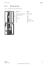


6.3
Installing the serial communication cable for RS485
SEMOD176344-1 v1
6.3.1
RS485 serial communication module
SEMOD176342-152 v6
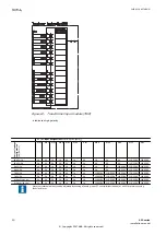
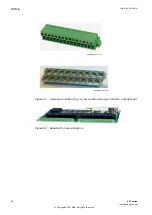
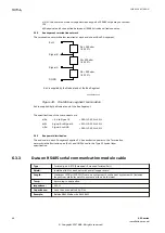
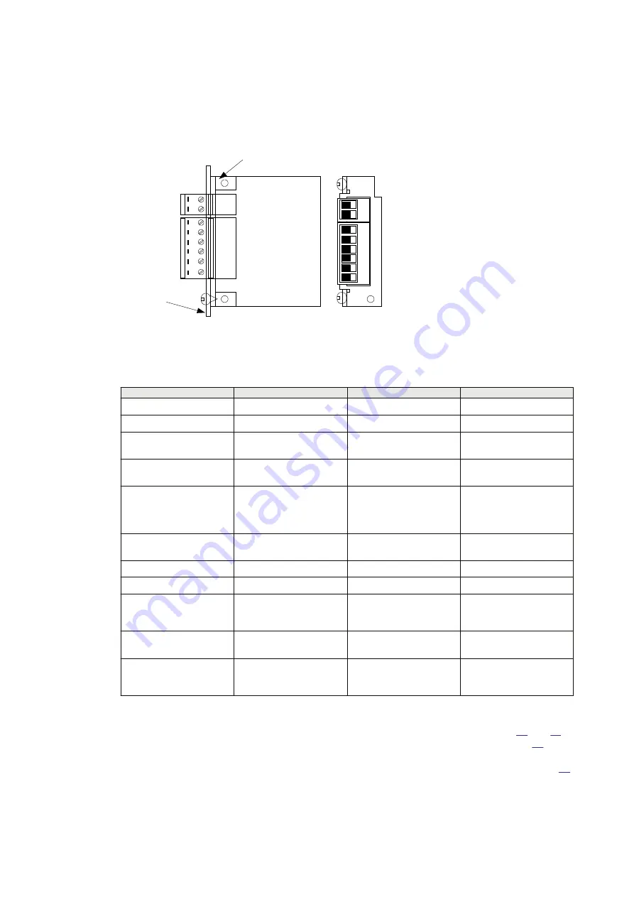
RS485
PWB
Screw
terminal
X1
Backplate
Screw
terminal
X3
Angle
bracket
1
2
4
5
6
3
1
2
en07000140.vsd
IEC07000140 V1 EN-US
Figure 25: The connection plate to the backplate with connectors and screws. This
figure also shows the pin numbering from the component side
Pin
Name 2-wire
Name 4-wire
Description
x3:1
soft earth
x3:2
soft earth
x1:1
RS485 +
TX+
Receive/transmit high or
transmit high
x1:2
RS485 –
TX-
Receive/transmit low or
transmit low
x1:3
Term
T-Term
Termination resistor for
transmitter (and receiver
in 2-wire case) (connect
to TX+)
x1:4
reserved
R-Term
Termination resistor for
receiver (connect to RX+)
x1:5
reserved
RX-
Receive low
x1:6
reserved
RX+
Receive high
2–wire:
Connect pin X1:1 to pin
X1:6 and pin X1:2 to pin
X1:5.
Termination (2-wire):
Connect pin X1:1 to pin
X1:3
Termination (4-wire):
Connect pin X1:1 to pin
X1:3 and pin X1:4 to pin
X1:6
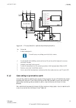
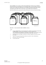
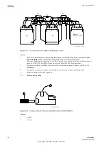
The distance between connection points should be < 1200 m (3000 ft), see Figures
.
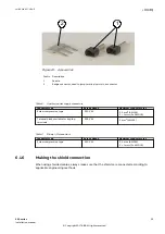
Only the outer shielding is connected to the IED with the cable clamp, shown in Figure
. The
cable shield shall be properly connected to the IED chassis with the cable clamp, where the
maximum open conductor length is 40 mm (1.57”) between clamp and terminals, see Figure
.
If double shielded cable is used, the inner cable shielding should be connected at the external
equipment end only. At the IED terminal end, the inner shield should be isolated. The inner and
Section 6
1MRK 514 027-UEN D
Connecting
42
650 series
Installation manual
© Copyright 2017 ABB. All rights reserved


