SEMOD53217-4 v14
1MRK006501-AF-TRM-IEC-6502P1 V1 EN-US
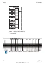
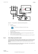
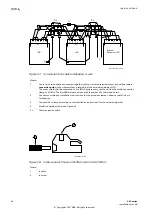
Figure 12: Transformer input module (TRM)
■
Indicates high polarity
CT/VT-input designation according to Figure
Current/voltage configuration (50/60/ Hz)
AI01
AI02
AI03
AI04
AI05
AI06
AI07
AI08
AI09
AI10
AI11
AI12
10I+2U, 1A
1A
1A
1A
1A
1A
1A
1A
1A
1A
1A
110-220V
110-220V
10I+2U, 5A
5A
5A
5A
5A
5A
5A
5A
5A
5A
5A
110-220V
110-220V
9I+3U, 1A
1A
1A
1A
1A
1A
1A
1A
1A
1A
110-220V
110-220V
110-220V
9I+3U, 5A
5A
5A
5A
5A
5A
5A
5A
5A
5A
110-220V
110-220V
110-220V
7I+5U, 1A
1A
1A
1A
1A
1A
1A
1A
110-220V
110-220V
110-220V
110-220V
110-220V
7I+5U, 5A
5A
5A
5A
5A
5A
5A
5A
110-220V
110-220V
110-220V
110-220V
110-220V
6I, 5A+1I, 1A+5U
5A
5A
5A
5A
5A
5A
1A
110-220V
110-220V
110-220V
110-220V
110-220V
3I, 5A+4I, 1A+5U
5A
5A
5A
1A
1A
1A
1A
110-220V
110-220V
110-220V
110-220V
110-220V
Note that internal polarity can be adjusted by setting of analog input CT neutral direction and/or on SMAI pre-processing
function blocks.
Section 6
1MRK 514 027-UEN D
Connecting
30
650 series
Installation manual
© Copyright 2017 ABB. All rights reserved


