ILLKO DIGIOHMPro, User Manual
The ILLKO DIGIOHMPro user manual is available for free download on our website. This comprehensive manual provides detailed instructions on how to use and maximize the potential of your ILLKO DIGIOHMPro device. Download it now from manualshive.com to ensure a seamless user experience.
Share
Download


Reviews:
No comments
Related manuals for DIGIOHMPro

CH
Brand: Eaton Pages: 8

AK-2-15
Brand: GE Pages: 10

AK-1-15 Series
Brand: GE Pages: 7

NDM3EU-225
Brand: nader Pages: 13
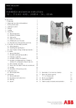
eVD4
Brand: ABB Pages: 72
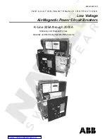
K-Line 1600A
Brand: ABB Pages: 36

AC500 V3
Brand: ABB Pages: 1029

Entelliguard G Env1
Brand: ABB Pages: 27
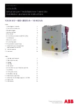
HD4-HPA Series
Brand: ABB Pages: 36

HD4/R
Brand: ABB Pages: 38

FSK II S +
Brand: ABB Pages: 36

20
Brand: ABB Pages: 15

5HK Series
Brand: ABB Pages: 16

VHK-R
Brand: ABB Pages: 16

VHK 20
Brand: ABB Pages: 34

VM1
Brand: ABB Pages: 60

GCE7002270R0107
Brand: ABB Pages: 24
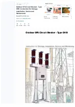
OHB
Brand: ABB Pages: 35


