8
8
8
7
5
6
3
4
2
7
5
6
7
5
6
3
4
2
3
4
2
1
1
2
1
1
1
8
7
5
6
3
4
2
2
1
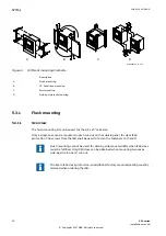
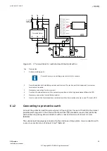
IEC06000180-2-en.vsd
IEC06000180 V2 EN-US
Figure 8:
IED (1/2 x 19”) mounted with a RHGS6 case containing a test switch module
equipped with only a test switch and a RX2 terminal base
5.3.5
Side-by-side flush mounting
IP10329-1 v1
5.3.5.1
Overview
M11975-3 v3
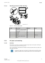
If IP54 is required it is not allowed to flush mount side by side mounted cases. If your
application demands side-by-side flush mounting, the side-by-side mounting details kit and
the 19” panel rack mounting kit must be used. The mounting kit has to be ordered separately.
The maximum size of the panel cut out is 19”.
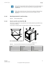
With side-by-side flush mounting installation, only IP class 20 is obtained. To
reach IP class 54, it is required to mount the IEDs separately. For cut out
dimensions of separately mounted IEDs, see section
.
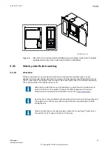
Use only the screws included in the mounting kit when mounting the plates and
the angles on the IED. Screws with wrong dimension may damage the PCBs
inside the IED.
Please contact factory for special add on plates for mounting FT switches on
the side (for 1/2 19" case) or bottom of the relay.
1MRK 514 027-UEN D
Section 5
Mounting
650 series
25
Installation manual
© Copyright 2017 ABB. All rights reserved

