9.3.2
Power swing detection ZMRPSB
M13888-2 v9
The aim is to verify that the settings of the Power swing detection function
ZMRPSB is according to the setting table and to verify that ZMRPSB operates as
expected.
Prepare the IED for verification of settings outlined in Section
Before starting this process, all impedance measuring zones shall be set and in
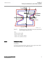
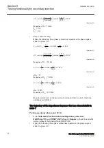
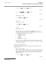
operation. Test the outer resistive boarder in forward and reverse direction,
RLdOutFw
and
RLdOutRv
and the inner reactive boarder in forward and reverse
direction
X1InFw
and
X1InRv
The corresponding resistive border for the inner resistive boundary and outer
resistive boundary is calculated automatically from the setting of
kLdRFw
and
kLdRRv
.
The inner zone of ZMRPSB must cover all zones by at least 10% margin.
The test is mainly divided into two parts, one which aim is to verify that the
settings are in accordance to the selectivity plan and a second part to verify the
operation of ZMRPSB. The proposed test points for validation of the settings are
numbered according to figure
Test of the interactions or combinations that are not configured are not considered
in this instruction.
Section 9
1MRK 506 383-UEN A
Testing functionality by secondary injection
78
Line distance protection REL650 2.2 IEC
Commissioning manual
Summary of Contents for REL650 series
Page 1: ...RELION 650 SERIES Line distance protection REL650 Version 2 2 Commissioning manual...
Page 2: ......
Page 24: ...18...
Page 28: ...22...
Page 38: ...32...
Page 54: ...48...
Page 58: ...52...
Page 178: ...172...
Page 182: ...176...
Page 188: ...182...
Page 196: ...190...
Page 206: ...200...
Page 207: ...201...


