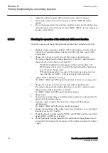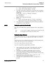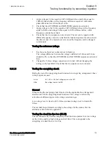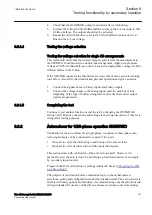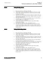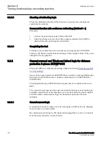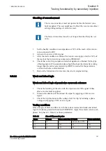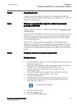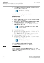
Possibly reset the counters to
Zero
. Counters are reset in the reset menu.
4.
Make arrangements for the simulation of the CB, for example as in Figure
5.
Make arrangements for indication, recording and time measurements.
The signals for CBCLOSED, START, CLOSECB, READY and other
relevant signals should preferably be arranged for event recording with time
tagging. If that is not possible, other means of time measurement and
recording should be arranged.
9.8.2.2
Switching the auto recloser to On and Off
On and Off
M12400-79 v9
1.
Set the
Operation
setting to
Off
and check the state.
2.
Set the
Operation
setting to
On
and check the state, including
SETON
and
READY
.
The circuit breaker should be closed and ready.
3.
If external control inputs OFF/ON are used, check that they work. Set
ExternalCtrl
=
On
and use the control inputs to switch On and Off, and check
the state of the function.
9.8.2.3
Verifying the auto recloser
M12400-91 v12
Select the test cases to be run according to what is applicable to the particular
application. It can be, for example,
•
three-phase single-shot auto reclosing
•
two-shot reclosing
•
single-phase and three-phase single-shot auto reclosing
Below, a case with single-phase and three-phase single-shot auto reclosing is
described.
1.
Set
Operation
=
On
.
2.
If the synchrocheck SESRSYN is not to be operated, ensure that the signal
SYNC input is activated. If SESRSYN is to be included, ensure that it is
supplied with the appropriate AC quantities.
3.
Simulate CB closed position by closing switch SC to make the BR relay start.
4.
Simulate CBREADY by closing the switch SRY, and leave it closed.
5.
Inject AC quantities to give a trip, for example, a one-phase trip, to the BR
and to the START input of the auto recloser.
Observe and preferably record the operation. The BR relay shall trip and
reclose (start). After reclosing, the SRY switch can be opened for about 5s
and then closed again.
The auto reclosing open time and the sequence should be checked, for
example in the event recording. Check also the operation indications
(disturbance report) and the operation counters on the local HMI under
Main
menu/Test/Function status/Control/AutoRecloser79,5(0–>1)/
SMBRREC(79,5(0–>)):x
Section 9
1MRK 506 383-UEN A
Testing functionality by secondary injection
144
Line distance protection REL650 2.2 IEC
Commissioning manual
Summary of Contents for REL650 series
Page 1: ...RELION 650 SERIES Line distance protection REL650 Version 2 2 Commissioning manual...
Page 2: ......
Page 24: ...18...
Page 28: ...22...
Page 38: ...32...
Page 54: ...48...
Page 58: ...52...
Page 178: ...172...
Page 182: ...176...
Page 188: ...182...
Page 196: ...190...
Page 206: ...200...
Page 207: ...201...


