


9.4.4
Four step residual overcurrent protection, (Zero sequence
or negative sequence directionality) EF4PTOC
SEMOD53296-3 v9
Prepare the IED for verification of settings outlined in Section
Values of the logical signals for D2PTOC are available on the local HMI under
Main menu/Tests/Function status/Current protection/
ResidualOverCurr4Step(51N_67N,4(IN>))/EF4PTOC(51N_67N;4(IN>)):x
,
where x = instance number.
The Signal Monitoring in PCM600 shows the same signals that are available on the
local HMI.
9.4.4.1
Four step directional earth fault protection
SEMOD53296-208 v7
1.
Connect the test set for single current injection to the appropriate IED
terminals.
Connect the injection current to terminals L1 and neutral.
2.
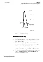
Set the injected polarizing voltage slightly larger than the set minimum
polarizing voltage (5% of Ur) and set the injection current to lag the voltage
by an angle equal to the set reference characteristic angle (
AngleRCA
), if the
forward directional function is selected.
If reverse directional function is selected, set the injection current to lag the
polarizing voltage by an angle equal to RCA+ 180°.
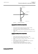
3.
Increase the injected current and note the value at which the studied step of
the function operates.
4.
Decrease the current slowly and note the reset value.
5.
If the test has been performed by injection of current in phase L1, repeat the
test, injecting current into terminals L2 and L3 with a polarizing voltage
connected to terminals L2, respectively L3.
6.
Block lower set steps when testing higher set steps according to the
instructions that follow.
7.
Connect a trip output contact to a timer.
8.
Set the injected current to 200% of the operate level of the tested step, switch
on the current and check the time delay.
For inverse time curves, check the operate time at a current equal to 110% of
the operate current for
txMin
.
9.
Check that all operate and start contacts operate according to the
configuration (signal matrixes)
10. Reverse the direction of the injected current and check that the step does not
operate.
11. Check that the protection does not operate when the polarizing voltage is
zero.
12. Repeat the above described tests for the higher set steps.
13. Finally, check that start and trip information is stored in the event menu.
Section 9
1MRK 506 383-UEN A
Testing functionality by secondary injection
106
Line distance protection REL650 2.2 IEC
Commissioning manual
Summary of Contents for REL650 series
Page 1: ...RELION 650 SERIES Line distance protection REL650 Version 2 2 Commissioning manual...
Page 2: ......
Page 24: ...18...
Page 28: ...22...
Page 38: ...32...
Page 54: ...48...
Page 58: ...52...
Page 178: ...172...
Page 182: ...176...
Page 188: ...182...
Page 196: ...190...
Page 206: ...200...
Page 207: ...201...


