


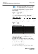


-3U
0
=U
ref
Operate area
Instrument
transformer
angle error
3I
0
(prim)
3I
0
(to prot)
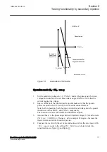
Characteristic after
angle compensation
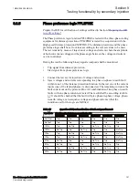
RCAcomp
IEC06000651-3-en.vsd
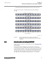
RCADir
= 0º
IEC06000651 V3 EN-US
Figure 19:
Explanation of RCAcomp
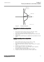
Operation mode 3I
0
· 3U
0
· cos φ
SEMOD175060-76 v8
1.
Set the polarizing voltage to 1.2 ·
UNRel>
and set the phase angle between
voltage and current to the set characteristic angle (
RCADir
). Note that the
current lagging the voltage.
2.
Inject current until the function picks up, and make sure that the operate
power is equal to the
SN>
setting for the set directional element.
Note that for operation, both the injected current and voltage must be greater
than the set values
INRel>
and
UNRel>
respectively.
The function activates the START and STDIRIN outputs.
3.
Assume that φ´ is the phase angle between injected voltage (3U
0
) and current
(3I
0
) i.e. φ´ =
RCADir
-φ. Change φ´ to for example 45 degrees. Increase the
injected current until the function operates.
4.
Compare the result with the set value and make sure that the new injected 3I
0
· 3U
0
· cos φ is equal to the setting
SN>
. Take the set characteristic into
1MRK 506 383-UEN A
Section 9
Testing functionality by secondary injection
Line distance protection REL650 2.2 IEC
111
Commissioning manual
Summary of Contents for REL650 series
Page 1: ...RELION 650 SERIES Line distance protection REL650 Version 2 2 Commissioning manual...
Page 2: ......
Page 24: ...18...
Page 28: ...22...
Page 38: ...32...
Page 54: ...48...
Page 58: ...52...
Page 178: ...172...
Page 182: ...176...
Page 188: ...182...
Page 196: ...190...
Page 206: ...200...
Page 207: ...201...


