I.L. 40-386.3
(10/94)
5-9
4.
Reclosing Initiation (RI) contacts RI-1 and RI-2 will not operate since the setting “RI type”
is “No RI”. Change “RI Type” to “ØG RI” and re-apply the fault current. RI-1 and RI-2 should
pick-up for approximately 400 ms (after the trip decision has been made).
Repeat the A phase-to-ground fault test and measure the trip time, which should be
less than 2 cycles.
STEP 7
Using the
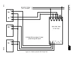
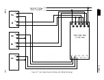
test connections shown in Figures 5-5 and 5-6,
repeat Step 6 above for B
phase-to-ground (BG) and C phase-to-ground (CG) faults respectively. The test voltag-
es are shown below:
For BG fault test, make connections
as shown in Figure 5-5
and adjust the voltages as
follows:
V
A
= 70 ang 0
°
V
B
= V
F
= 30 ang -120
°
V
C
= 70 ang 120
°
Apply current to the B phase current input as shown. The current required to trip is
4.00 amps
±
5% at an angle of 75
°
lagging the fault voltage.
When the relay trips, remove the fault current.
Zone
1 and BG LED’s will light. The LCD
display will indicate the fault distance. Using the RAISE and LOWER push-buttons the
complete fault record can be reviewed.
See Table 4-3 for a description of the displayed
fault data quantities.
The significant quantities to review are:
Fault Type – “FLT Type” “BG”
Targets – “Zone1G” “Yes”
Fault Voltages (VA, VB, VC, 3V0) and Currents (IA, IB, IC, IP)
For CG fault test make connections
as shown in Figure 5-6
and adjust the voltages as
follows:
V
A
= 70 ang 0
°
V
B
= 70 ang -120
°
V
C
= V
F
= 30 ang 120
°
Apply current to the C phase current input as shown. The current required to trip is
4.00 Amps
±
5% at the angle of 75
°
lagging the fault voltage.
When the relay trips, remove the fault current. Zone1 and CG LED’s will light. The LCD
display will indicate the fault distance. Using the RAISE and LOER push-buttons the
complete fault record can be reviewed.
See Table 4-4 for a description of the displayed
fault data quantities.
The significant quantities to review are:
Summary of Contents for REL 301
Page 1: ......
Page 8: ......
Page 17: ...I L 40 386 3 1 10 10 94 2682F39 Sheet 1 of 2 Sub 2 Figure 1 2 REL 301 302 Layout Vertical...
Page 18: ...I L 40 386 3 10 94 1 11 2682F39 Sheet 2 of 2 Sub 2 Figure 1 3 REL 301 302 Layout Horizontal...
Page 19: ......
Page 20: ......
Page 44: ......
Page 46: ......
Page 48: ......
Page 49: ......
Page 51: ......
Page 53: ......
Page 54: ......
Page 55: ......
Page 56: ......
Page 57: ......
Page 60: ......
Page 62: ...I L 40 386 3 10 94 2 41 Figure 2 32 CO 2 Curve Characteristics 619596 Sub 2...
Page 63: ...I L 40 386 3 2 42 10 94 Figure 2 33 CO 5 Curve Characteristic 619597 Sub 2...
Page 64: ...I L 40 386 3 10 94 2 43 Figure 2 34 CO 6 Curve Characteristic 619598 Sub 2...
Page 65: ...I L 40 386 3 2 44 10 94 Figure 2 35 CO 7 Curve Characteristic 619599 Sub 2...
Page 66: ...I L 40 386 3 10 94 2 45 Figure 2 36 CO 8 Curve Characteristic 619600 Sub 2...
Page 67: ...I L 40 386 3 2 46 10 94 Figure 2 37 CO 9 Curve Characteristic 619601 Sub 2...
Page 68: ...I L 40 386 3 10 94 2 47 Figure 2 38 CO 11 Curve Characteristic 619602 Sub 2...


