Quick-Start Guide
IN-LINELINC RELAY
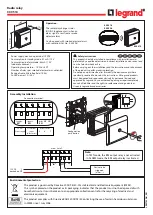
In-LineLinc Relay (#2475S) - 10 Amp
SET Button
P
Prre
ep
pa
arra
attiio
on
n
IIn
ns
stta
alllla
attiio
on
n s
sh
ho
ou
ulld
d b
be
e p
pe
errffo
orrm
me
ed
d o
on
nllyy b
byy a
a q
qu
ua
alliiffiie
ed
d e
elle
ec
cttrriic
ciia
an
n o
orr b
byy a
a h
ho
om
me
eo
ow
wn
ne
err w
wh
ho
o iis
s ffa
am
miilliia
arr a
an
nd
d c
co
om
mffo
orrtta
ab
blle
e w
wiitth
h e
elle
ec
cttrriic
ca
all
c
ciirrc
cu
uiittrryy.. IIff tth
he
erre
e a
arre
e a
an
nyy q
qu
ue
es
sttiio
on
ns
s,, c
co
on
ns
su
ulltt a
an
n e
elle
ec
cttrriic
ciia
an
n.. F
Fo
orr s
se
ettu
up
p q
qu
ue
es
sttiio
on
ns
s c
co
on
ntta
ac
ctt T
Te
ec
ch
h S
Su
up
pp
po
orrtt a
att S
Sm
ma
arrttL
La
ab
bs
s ffo
orr g
gu
uiid
da
an
nc
ce
e..
T
To
oo
olls
s yyo
ou
u w
wiillll n
ne
ee
ed
d::
•A Phillips screwdriver
•A wire cutter/stripper
•A voltage tester to identify wires inside the junction box
N
Ne
ee
ed
d H
He
ellp
p?
? F
Fo
orr a
as
ss
siis
stta
an
nc
ce
e c
ca
allll yyo
ou
urr ffrriie
en
nd
dllyy
s
su
up
pp
po
orrtt p
pe
errs
so
on
n @
@ 8
86
66
6--2
24
43
3--8
80
01
18
8
Status LED
Installing Your In-LineLinc Relay
Step 1.
It is recommended that you have properly installed at least two SignaLinc RF Signal Enhancers #2442 (sold separately).
Step 2.
Write down the INSTEON ID and location of the fixture you want to control (e.g. 01.F7.G5, Mike’s Bedroom Light).
Step 3.
At the circuit breaker or fuse panel, disconnect the power to the circuit(s) supplying power to the fixture.
Step 4.
Disconnect the wires from the fixture you will be controlling and ensure you have 1/2” of bare wire on the ends.
Step 5.
Follow the diagram to identify and connect the LINE, LOAD, NEUTRAL, and GROUND wires. If the colors of the wires do
not match the diagram, be sure you have identified the wires correctly before connecting them.
Step 6.
Ensure that all wire connectors are firmly attached and that there is no
exposed copper except for the GROUND wire.
Step 7.
Prior to reinstalling the fixture, turn the circuit breaker back on or
reinstall the fuse.
Step 8.
Select the INSTEON-Enabled Controller you would like to use
to control the In-LineLinc and set it to Linking Mode. For most
controllers, press and hold the On button for 10 seconds. The
LED will begin to blink.
Step 9.
Press and hold the SET Button (as pictured above) on the
In-LineLinc for 3 seconds. The Status LED will flash upon
successful linking and return to steady on. Test by pressing On
and Off on your controller. You can also use software such as
HouseLinc Desktop, which will require the INSTEON ID from
Step 2.
Step 10.
Place the In-LineLinc into the junction box.
Note: Screw Tabs may be removed if not needed.
Step 11.
Reinstall the fixture.
T
TM
M
Your new INSTEON
TM
In-LineLinc Relay allows you to remotely control any light or
fan in your home at the touch of a button.
•A probe that is non-conductive to press the SET Button (e.g. pencil)
Screw Tab
Screw Tab