


Disassembly/Assembly
Guidelines
IRB 6400
Page 6 - 6
Axes 2 & 3 Guidelines
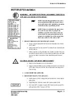
GEAR REDUCTION UNIT (S35) Installation
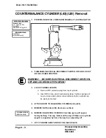
WARNING! BE SURE ELECTRICAL DISCONNECT SWITCH IS
OFF AND LOCKED IN OFF POSITION.
NOTE: The following guideline is for axis 3 gear reduction
unit installation (right side of robot). Axis 2 gear reduction
unit (left side of robot) installation procedure is identical
unless specifically noted.
1.
CLEAN ALL COMPONENTS.
2.
INSTALL GUIDE PINS:
a.
Thread two M12 x 200 threaded rods into two horizontally opp o-
site threaded holes that are used for screws (S31). These rods
will serve to hold friction ring (S32) in place and to guide RV into
position. (Use holes located at approximately 10 and 2 o’clock. )
3.
MOUNT GEAR REDUCTION UNIT (S35):
a.
Lightly grease O-Ring (S33) with lubricating grease (S74).
Position O-Ring in place.
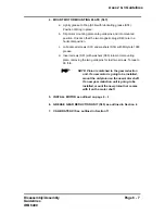
b.
Lightly grease friction ring (S32) and position in place on guide
rods.
c.
Position friction ring (S34) in place.
d.
Slip gear reduction unit onto guide pins and into mounted position
in frame housing (S21).
e.
Use lifting tool (#6896 0011-YL) to lift RV into position .
f.
Lubricate three screws (S29) and washers (S28) with Molycote
1000 and insert through center of gear reduction unit into M12
threaded holes. Start threads, but do not tighten .
g.
Lubricate three screws (27) and washers (S26) with Molycote
1000 and insert through center of gear reduction unit into M16
threaded holes. Start threads, but do not tighten .
h.
Check that all holes are aligned and components are correctly
positioned.
i.
Torque M16 screws (S27) to 224 ft-lb.
j.
Torque M12 screws (S29) to 90 ft-lb.
Molycote 1000 Grease
Torque Wrench (90-221 ft-lb)
REFERENCE DRAWINGS
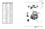
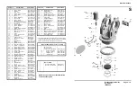
Exploded View:
“S” (pg 6-23, 12-2)
Assemblies:
3HAA 0001-EP (pg 13-10)
Hand Tools
M12x200 Threaded Rods (2)
Lubricating Grease
REQUIRED TOOLS
3HAA 0001-RB (pg 13-6)
3HAA 0001-RB (pg 13-7)
3HAA 0001-RB (pg 13-4)
3HAB 4162-2 (pg 13-9)
3HAB 4162-2 (pg 13-8)
3HAB 4163-2 (pg 13-23)
3HAB 4167-2 (pg 13-11)
3HAA 0001-AAS (pg 14-A)
3HAA 0001-AAO (pg 14-E)
3HAB 4252-2 (pg 14-I)
Loctite 242
E
E
GEAR UNIT WEIGHS
APPROX. 125 LB.
6896 0011-YL
Summary of Contents for IRB6400
Page 5: ...Disassembly Assembly Guidelines IRB 6400 Introduction SECTION 1 ...
Page 15: ...Disassembly Assembly Guidelines IRB 6400 Safety SECTION 2 ...
Page 26: ...Disassembly Assembly Guidelines IRB 6400 Robot Handling SECTION 3 ...
Page 34: ...Disassembly Assembly Guidelines IRB 6400 Maintenance SECTION 4 ...
Page 61: ...Disassembly Assembly Guidelines IRB 6400 Axis 1 SECTION 5 Disassembly Assembly ...
Page 81: ...Disassembly Assembly Guidelines IRB 6400 Axes 2 3 SECTION 6 Disassembly Assembly ...
Page 107: ...Disassembly Assembly Guidelines IRB 6400 Axis 4 SECTION 7 Disassembly Assembly ...
Page 131: ...Disassembly Assembly Guidelines IRB 6400 Axis 5 SECTION 8 Disassembly Assembly ...
Page 143: ...Disassembly Assembly Guidelines IRB 6400 Axis 6 SECTION 9 Disassembly Assembly ...
Page 152: ...Disassembly Assembly Guidelines IRB 6400 Cables Guidelines SECTION 10 ...
Page 169: ...Disassembly Assembly Guidelines IRB 6400 Robot Calibration SECTION 11 ...
Page 171: ...Disassembly Assembly Guidelines IRB6400 Page 11 2 RobotCalibration NOTES ...
Page 196: ...Page 11 27 RobotCalibration Disassembly Assembly Guidelines IRB6400 NOTES ...
Page 197: ...Disassembly Assembly Guidelines IRB6400 Page 11 28 RobotCalibration NOTES ...
Page 198: ...Disassembly Assembly Guidelines IRB 6400 Parts Lists Illustrations SECTION 12 ...
Page 209: ...Disassembly Assembly Guidelines IRB 6400 Reference SECTION 13 Mechanical Layouts ...
Page 211: ...Disassembly Assembly Guidelines IRB 6400 Reference SECTION 14 Cable Layouts ...


