


Disassembly/Assembly
Guidelines
IRB 6400
Page 10 - 10
Cables Guidelines
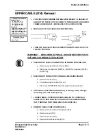
AXIS 6 MOTOR (F10) CABLE Installation
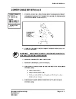
WARNING! BE SURE ELECTRICAL DISCONNECT SWITCH IS
OFF AND LOCKED IN OFF POSITION!
1.
POSITION AXIS 6 CABLING FOR INSTALLATION):
a.
Lay cable along tube (U19) and in position for installation .
b.
Thread connectors through angle channel at rear of motor (F10).
Connect connectors R4.MP6, R4.FB6, & R4.PTC6 .
c.
Connect connectors R3.MP6 & R3.FB6 inside junction box,
inside left side of tube (U19). Mount cover to junction box.
Ttighten screws (U15), if loosened when cable was removed .
2.
CONNECT CABLE CARRIER TO WRIST ASSEMBLY (U10) WITH
SCREWS (U16) AND (U17).
3.
INSTALL ANGLE CHANNEL OVER CABLE PIT ON MOTOR (F10).
USE SEALANT (F28). BE SURE JOINT IS LIQUID TIGHT
.
4.
INSTALL COVER (F9) WITH SCREWS (F7) AND WASHERS (F8). USE
SEALANT (F28). BE SURE JOINT IS LIQUID TIGHT.
5.
INSTALL COVER (U7) AND GASKET (U9) WITH SCREWS (U6). USE
SEALANT (U8). BE SURE JOINT IS LIQUID TIGHT.
6.
INSTALL COVER (U5) WITH SCREWS (U4).
7.
CALIBRATE AXES as outlined in Section 11.
E
E
REFERENCE DRAWINGS
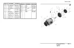
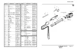
Exploded Views:
Assemblies:
Hand Tools
REQUIRED TOOLS
3HAB 4163-2 (pg 13-22)
3HAA 0001-AAS (pg 14-A)
3HAB 4254-2 (pg 14-J)
3HAA 0001-AAH (pg 13-13)
“U” (pg 10-13, 12-4)
“F” (pg 10-15, 12-6)
3HAA 0001-ACA (pg 14-D)
3HAA 0001-GX (pg 13-18)
Summary of Contents for IRB6400
Page 5: ...Disassembly Assembly Guidelines IRB 6400 Introduction SECTION 1 ...
Page 15: ...Disassembly Assembly Guidelines IRB 6400 Safety SECTION 2 ...
Page 26: ...Disassembly Assembly Guidelines IRB 6400 Robot Handling SECTION 3 ...
Page 34: ...Disassembly Assembly Guidelines IRB 6400 Maintenance SECTION 4 ...
Page 61: ...Disassembly Assembly Guidelines IRB 6400 Axis 1 SECTION 5 Disassembly Assembly ...
Page 81: ...Disassembly Assembly Guidelines IRB 6400 Axes 2 3 SECTION 6 Disassembly Assembly ...
Page 107: ...Disassembly Assembly Guidelines IRB 6400 Axis 4 SECTION 7 Disassembly Assembly ...
Page 131: ...Disassembly Assembly Guidelines IRB 6400 Axis 5 SECTION 8 Disassembly Assembly ...
Page 143: ...Disassembly Assembly Guidelines IRB 6400 Axis 6 SECTION 9 Disassembly Assembly ...
Page 152: ...Disassembly Assembly Guidelines IRB 6400 Cables Guidelines SECTION 10 ...
Page 169: ...Disassembly Assembly Guidelines IRB 6400 Robot Calibration SECTION 11 ...
Page 171: ...Disassembly Assembly Guidelines IRB6400 Page 11 2 RobotCalibration NOTES ...
Page 196: ...Page 11 27 RobotCalibration Disassembly Assembly Guidelines IRB6400 NOTES ...
Page 197: ...Disassembly Assembly Guidelines IRB6400 Page 11 28 RobotCalibration NOTES ...
Page 198: ...Disassembly Assembly Guidelines IRB 6400 Parts Lists Illustrations SECTION 12 ...
Page 209: ...Disassembly Assembly Guidelines IRB 6400 Reference SECTION 13 Mechanical Layouts ...
Page 211: ...Disassembly Assembly Guidelines IRB 6400 Reference SECTION 14 Cable Layouts ...


