


Disassembly/Assembly
Guidelines
IRB 6400
Page 2 - 3
Safety
SAFETY FEATURES
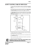
Selection of Operating Mode
The robot can be operated either manually or automatically. In Manual
mode, the robot can only be operated using the teach pendant, not by any
external equipment.
Reduced Speed
The speed can be limited to a maximum of 250 mm/s. A speed limitation
applies not only to the Tool Center Point (TCP), but to all parts of the robot.
It is also possible to monitor the speed of equipment mounted on the robot .
Overspeed Protection
The speed of the robot is monitored by two independent computers .
Emergency Stop (E-Stop)
There is one emergency stop push button on the control panel, and anot h-
er on the teach pendant. Additional emergency stop buttons can be co n-
nected to the robot’s safety chain circuit .
Safeguarded Space Stop
These include: Manual Stop, Auto Stop, General Stop, E-Stop, Limit Stop.
The robot has a number of electrical inputs which can be used to connect
external safety equipment, such as safety gates and light curtains. This a l-
lows the robot’s safety functions to be activated both by peripheral equi p-
ment and by the robot itself.
Delayed Safeguarded Space Stop
Such as a Hold circuit. A delayed stop gives a smooth stop. The robot
stops in the same way as a normal program stop with no deviation from
programmed path. After 1-2 seconds the power supplied to the motors
shuts off.
Restricting the Working Space
The movement of each of the axes 1-6 can be restricted using software
limits. Axes 1-3 can also be restricted by means of an adjustable mecha n-
ical stop. Axis 1 & 2 can be restricted using an Electrical Limit switch .
Enabling Device
You must use the Enabling Device on the Teach Pendant to start the motor
before you can move the robot when in Manual modes. The Enabling D e-
vice has a switch with three positions, meaning that all robot movements
stop when either the Enabling Device is pushed fully IN, or when it is r e-
leased completely. This makes the robot safer to operate .
Hold-to-Run Control
“Hold-to-run” means that you must hold down the Program Start button or
step (forward or backward) in order to move the robot. When the button is
released, the robot will stop. The hold-to-run function makes programming
test safer. This feature can be disabled for manual reduced speed mode .
Summary of Contents for IRB6400
Page 5: ...Disassembly Assembly Guidelines IRB 6400 Introduction SECTION 1 ...
Page 15: ...Disassembly Assembly Guidelines IRB 6400 Safety SECTION 2 ...
Page 26: ...Disassembly Assembly Guidelines IRB 6400 Robot Handling SECTION 3 ...
Page 34: ...Disassembly Assembly Guidelines IRB 6400 Maintenance SECTION 4 ...
Page 61: ...Disassembly Assembly Guidelines IRB 6400 Axis 1 SECTION 5 Disassembly Assembly ...
Page 81: ...Disassembly Assembly Guidelines IRB 6400 Axes 2 3 SECTION 6 Disassembly Assembly ...
Page 107: ...Disassembly Assembly Guidelines IRB 6400 Axis 4 SECTION 7 Disassembly Assembly ...
Page 131: ...Disassembly Assembly Guidelines IRB 6400 Axis 5 SECTION 8 Disassembly Assembly ...
Page 143: ...Disassembly Assembly Guidelines IRB 6400 Axis 6 SECTION 9 Disassembly Assembly ...
Page 152: ...Disassembly Assembly Guidelines IRB 6400 Cables Guidelines SECTION 10 ...
Page 169: ...Disassembly Assembly Guidelines IRB 6400 Robot Calibration SECTION 11 ...
Page 171: ...Disassembly Assembly Guidelines IRB6400 Page 11 2 RobotCalibration NOTES ...
Page 196: ...Page 11 27 RobotCalibration Disassembly Assembly Guidelines IRB6400 NOTES ...
Page 197: ...Disassembly Assembly Guidelines IRB6400 Page 11 28 RobotCalibration NOTES ...
Page 198: ...Disassembly Assembly Guidelines IRB 6400 Parts Lists Illustrations SECTION 12 ...
Page 209: ...Disassembly Assembly Guidelines IRB 6400 Reference SECTION 13 Mechanical Layouts ...
Page 211: ...Disassembly Assembly Guidelines IRB 6400 Reference SECTION 14 Cable Layouts ...


