


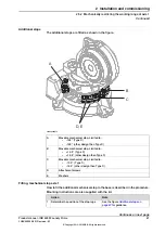
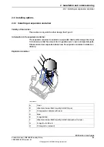
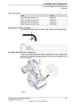

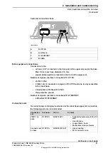
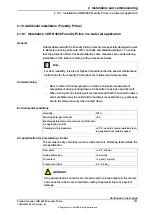

Additional stops
The additional stops are fitted as shown in the figure.
A
B
C
D, E
xx0800000273
Movable mechanical stop. Limited to:
•
-126° (Type C)
•
-129° (other design than Type C)
A
Movable mechanical stop. Limited to:
•
+13.5° (Type C)
•
+16.5° (other design than Type C)
B
Movable mechanical stop. Limited to:
•
-13.5° (Type C)
•
-16.5° (other design than Type C)
C
Attachment screws
D
Washers
E
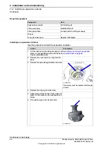
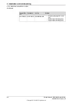
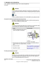
Fitting, mechanical stop axis 1
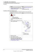
How to fit the additional mechanical stop to the base is described in the procedure.
Mounting instructions are also supplied with the kit.
Note
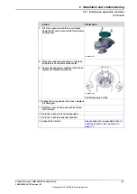
Action
See the figure
for guidance.
Determine the position of the stop lugs.
1
Continues on next page
Product manual - IRB 4600 Foundry Prime
87
3HAC040585-001 Revision: M
© Copyright 2013-2018 ABB. All rights reserved.
2 Installation and commissioning
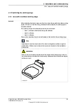
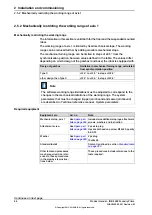
2.5.2 Mechanically restricting the working range of axis 1
Continued
Summary of Contents for IRB 4600 Foundry Prime
Page 1: ...ROBOTICS Product manual IRB 4600 Foundry Prime ...
Page 106: ...This page is intentionally left blank ...
Page 194: ...This page is intentionally left blank ...
Page 398: ...This page is intentionally left blank ...
Page 400: ...This page is intentionally left blank ...
Page 406: ......
Page 407: ......


