


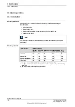


3.7 Measuring activities
3.7.1 Measuring backlash axis 4
General
This section describes measuring of the backlash on axis 4.
DANGER
Turn off all electrical power, hydraulic and pneumatic pressure supplies before
entering the workspace of the manipulator.
Also read the safety sections:
•
Pneumatic or hydraulic related hazards on page 32
•
•
Maintenance and repair on page 34
Required equipment and references
Note
Required equipment
Indicator clock
Dynamometer
(square tube, length = min. 250 mm)
Tool
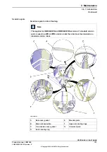
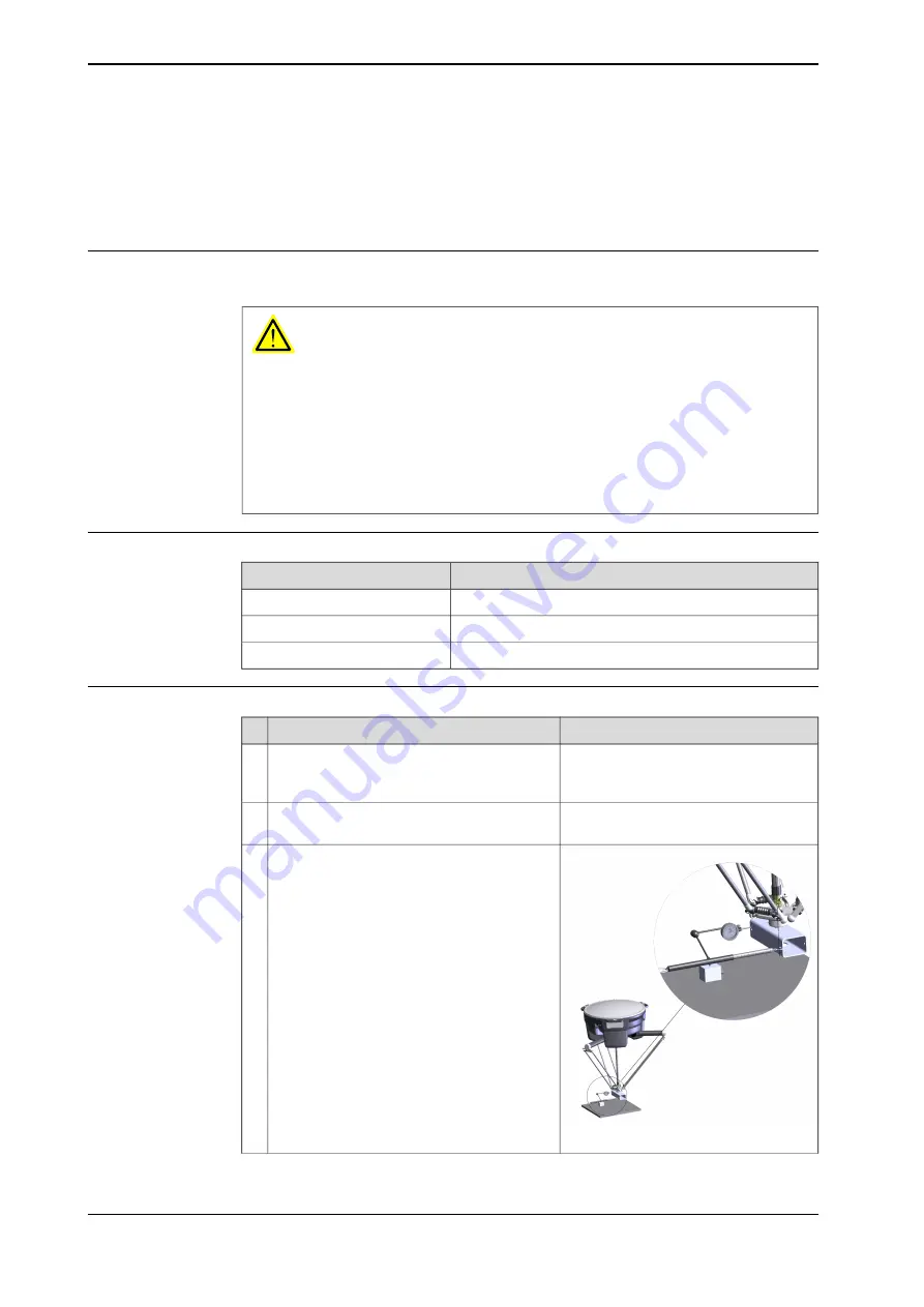
Measuring backlash
Note
Action
For fastening of tool on robot, see hole
pattern in
Attache the tool on manipulator.
1
Place the indicator clock on a metallic surface
placed underneath the manipulator.
2
xx1700000046
Apply torque 1 Nm, i.e. 10N on a distance of
100 mm from center of rotation.
3
Continues on next page
146
Product manual - IRB 360
3HAC030005-001 Revision: Z
© Copyright 2008-2021 ABB. All rights reserved.
3 Maintenance
3.7.1 Measuring backlash axis 4
Summary of Contents for IRB 360
Page 1: ...ROBOTICS Product manual IRB 360 ...
Page 8: ...This page is intentionally left blank ...
Page 266: ...This page is intentionally left blank ...
Page 268: ...This page is intentionally left blank ...
Page 271: ......


