


Single and Dual Input Analyzers for Low Level Conductivity
AX410, AX411, AX413, AX416, AX418, AX450, AX455 & AX456
6 INSTALLATION
IM/AX4CO Issue 11
55
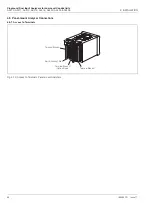
6.3.2 Cable Entry Knockouts, Wall-/Pipe-mount Analyzer
The analyzer is supplied with 7 cable glands, one fitted and six to be fitted, as required, by the user - see Fig. 6.7.
Fig. 6.7 Cable Entry Knockouts, Wall-/Pipe-mount Analyzer
5
Place the blade of a small, flat bladed screwdriver
into the knockout groove and tap the
screwdriver smartly to remove the knockout
(see
Note
below)
Smooth the edges of the hole
with a small round or half-round file
Fit an 'O' ring seal to the the cable gland
Insert the cable gland into the hole
in the analyzer case from the outside
Secure the cable
gland with the nut
2
3
4
6
Cable entry knockouts
Factory-fitted cable gland
1
Release the four captive
screws and remove
the terminal cover plate


