


Single and Dual Input Analyzers for Low Level Conductivity
AX410, AX411, AX413, AX416, AX418, AX450, AX455 & AX456
5 PROGRAMMING
IM/AX4CO Issue 11
37
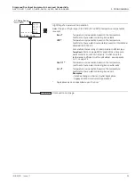
Default Output
Select the system reaction to failure:
Off
On
Hold
-
-
-
Ignore failure and continue operation.
Stop on failure. This drives the analog output to the level set in the
Default Val
frame below.
Hold the analog output at the value prior to the failure.
Default Value
The level to which the analog output is driven if a failure occurs.
Set the value between 0.00 and 22.00mA.
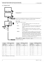
Output 2 configuration (and Outputs 3 and 4 if option board fitted
and
analog features
enabled - see section 7.3, page 62) is identical to Output 1 configuration.
Option board fitted
and
analog features enabled (Section 7.3) - see section 5.7, page
41.
Option board fitted
and
Serial Communications feature enabled (Section 7.3) - see
Supplementary Manual
PROFIBUS Datalink Description (IM/PROBUS)
.
Single input analyzer
and
option board not fitted - see section 5.8, page 42.
Dual input analyzer
and
option board not fitted - see section 5.9, page 47.
AO1: Default O/P
-----
mA
Off
On
Hold
AO1: Default Val
12.00
mA
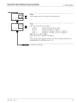
Config. Output 1
Config. Output 2
CONFIG. SERIAL
CONFIG. CLOCK
CONFIG. SECURITY
CONFIG. CONTROL
Config. Output 1
On
Off
or
Hold


