Safety instructions
14
Safety in installation and maintenance
Electrical safety
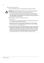
These warnings are intended for all who work on the drive, motor cable or motor.
WARNING!
Ignoring the following instructions can cause physical injury or death, or
damage to the equipment:
•
Only qualified electricians are allowed to install and maintain the drive.
• Before working on the drive, isolate the whole drive from the supply. The main
switch on the cabinet door does not remove the voltage from the input busbars of
the drive.
• Never work on the drive, motor cable or motor when main power is applied. After
switching off the input power, always wait for 5 min to let the intermediate circuit
capacitors discharge before you start working on the drive, motor or motor cable.
Measure the voltage b and - DC busbars with a multimeter (impedance
at least 1 Mohm) to ensure that the drive is discharged before beginning work.
• Apply temporary grounding before working on the unit.
• Do not work on the control cables when power is applied to the drive or to the
external control circuits. Externally supplied control circuits may cause dangerous
voltages inside the drive even when the main power on the drive is switched off.
• Do not make any insulation or voltage withstand tests on the drive or drive
modules.
• When reconnecting the motor cable, always check that the phase order is correct.
• When joining shipping splits (if any), check the cable connections at the joints
before switching on the supply voltage.
• Live parts on the inside of the doors are protected against direct contact. Pay
special attention when handling metallic shrouds.
Note:
• The motor cable terminals on the drive are at a dangerously high voltage when
the input power is on, regardless of whether the motor is running or not.
• The drive DC bus and brake resistor terminals (R+, R-, R1.1, R1.2, R1.3, R2.1,
R2.2. and R2.3) carry dangerous voltage (over 500 V).
• Depending on the external wiring, dangerous voltages (115 V, 220 V or 230 V)
may be present on the relay outputs of the drive system.
• The Prevention of unexpected start function (Q950) and the Safe torque
off function (Q968) do not remove the voltage from the main and auxiliary
circuits.
• At installation sites above 2000 m (6562 ft), the terminals of the RMIO board and
optional modules attached to the board do not fulfil the Protective Extra Low
Voltage (PELV) requirements stated in EN 61800-5-1.
Summary of Contents for ACS800-17LC
Page 1: ...ABB industrial drives Hardware manual ACS800 17LC Drives 55 to 5200 kW ...
Page 4: ......
Page 10: ...Update notice 6 ...
Page 18: ...Table of contents 12 ...
Page 26: ...Safety instructions 20 ...
Page 32: ...Introduction to the manual 26 ...
Page 60: ...Hardware description 54 ...
Page 74: ...Mechanical installation 68 ...
Page 114: ...Electrical installation 108 ...
Page 142: ...Maintenance 136 ...
Page 150: ...Internal cooling circuit 144 ...
Page 179: ...Dimensions 173 Frame sizes R7i R7i and R8i R8i bottom entry exit ...
Page 180: ...Dimensions 174 Frame sizes R7i R7i and R8i R8i marine units C121 ...
Page 182: ...www abb com drives www abb com drivespartners Contact us 3AUA0000065339 Rev B EN 2016 06 07 ...


